Videos
MCAT-Style Passage Problems
Lightbulb Failure
You’ve probably observed that the most common time for an incandescent lightbulb to fail is the moment when it is turned on. Let’s look at the properties of the bulb’s filament to see why this happens.
The current in the tungsten filament of a lightbulb heats the filament until it glows. The filament is so hot that some of the atoms on its surface fly off and end up sticking on a cooler part of the bulb. Thus the filament gets progressively thinner as the bulb ages. There will certainly be one spot on the filament that is a bit thinner than elsewhere. This thin segment will have a higher resistance than the surrounding filament. More power will be dissipated at this spot, so it won’t only be a thin spot, it also will be a hot spot.
Now, let’s look at the resistance of the filament. The graph in Figure P22.70 shows data for the current in a lightbulb as a function of the potential difference across it. The graph is not linear, so the filament is not an ohmic material with a constant resistance, However we can define the resistance at any particular potential difference ∆V to be R = ∆V/I. This ratio, and hence the resistance, increases with ∆V and thus with temperature.
Figure P22. 70
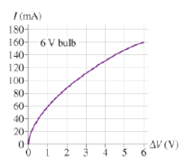
When the bulb is turned on, the filament is cold and its resistance is much lower than during normal, high-temperature operation. The low resistance causes a surge of higher-than-normal current lasting a fraction of a second until the filament heats up. Because power dissipation is I2R, the power dissipated during this first fraction of a second is much larger than the bulb’s rated power. This current surge concentrates the power dissipation at the high-resistance thin spot, perhaps melting it and breaking the filament.
71. As the bulb ages, the resistance of the filament
A. Increases.
B. Decreases.
C. Stays the same.
Want to see the full answer?
Check out a sample textbook solution
Chapter 22 Solutions
College Physics: A Strategic Approach (4th Edition)
Additional Science Textbook Solutions
Lecture- Tutorials for Introductory Astronomy
College Physics
University Physics with Modern Physics (14th Edition)
University Physics Volume 1
Conceptual Physics (12th Edition)
An Introduction to Thermal Physics


- Four resistors are connected to a battery as shown in Figure P21.40. The current in the battery is I, the battery emf is , and the resistor values are R1 = R, R2 = 2R, R3 = 4R, and R4 = 3R. (a) Rank the resistors according to the potential difference across them, from largest to smallest. Note any cases of equal potential differences. (b) Determine the potential difference across each resistor in terms of . (c) Rank the resistors according to the current in them, from largest to smallest. Note any cases of equal currents. (d) Determine the current in each resistor in terms of I. (e) If R3 is increased, what happens to the current in each of the resistors? (f) In the limit that R3 , what are the new values of the current in each resistor in terms of I, the original current in the battery? Figure P21.40arrow_forwardA 20.00-V battery is used to supply current to a 10-k resistor. Assume the voltage drop across any wires used for connections is negligible, (a) What is the current through the resistor? (b) What is the power dissipated by the resistor? (c) What is the power input from the battery; assuming all the electrical power is dissipated by the resistor? (d) What happens to the energy dissipated by the resistor?arrow_forwardRalph has three resistors, R1, R2, and R3, connected in series. When connected to an ideal emf source E1, current I1 flows through the resistors. a. If the resistors are instead connected to a second source with E2=2E1, what is the new current through the resistors in terms of the first current? b. Show that, if each resistance is doubled and the resistors are connected in series to the second emf source, the current through the resistors is equal to I1.arrow_forward
- Three 100- resistors are connected as shown in Figure P21.41 The maximum power that can safely be delivered to any one resistor is 25.0 W. (a) What is the maximum potential difference that can be applied to the terminals a and b? (b) For the voltage determined in part (a), what is the power delivered to each resistor? (c) What is the total power delivered to the combination of resistors?arrow_forwardYou’ve probably observed that the most common time for an incandescent lightbulb to fail is the moment when it is turned on. Let’s look at the properties of the bulb’s filament to see why this happens.The current in the tungsten filament of a lightbulb heats the filament until it glows. The filament is so hot that some of the atoms on its surface fly off and end up sticking on a cooler part of the bulb. Thus the filament gets progressively thinner as the bulb ages. There will certainly be one spot on the filament that is a bit thinner than elsewhere. This thin segment will have a higher resistance than the surrounding filament. More power will be dissipated at this spot, so it won’t only be a thin spot, it also will be a hot spot.Now, let’s look at the resistance of the filament. The graph in Figure P22.70 shows data for the current in a lightbulb as a function of the potential difference across it. The graph is not linear, so the filament is not an ohmic material with a constant…arrow_forwardYou’ve probably observed that the most common time for an incandescent lightbulb to fail is the moment when it is turned on. Let’s look at the properties of the bulb’s filament to see why this happens.The current in the tungsten filament of a lightbulb heats the filament until it glows. The filament is so hot that some of the atoms on its surface fly off and end up sticking on a cooler part of the bulb. Thus the filament gets progressively thinner as the bulb ages. There will certainly be one spot on the filament that is a bit thinner than elsewhere. This thin segment will have a higher resistance than the surrounding filament. More power will be dissipated at this spot, so it won’t only be a thin spot, it also will be a hot spot.Now, let’s look at the resistance of the filament. The graph in Figure P22.70 shows data for the current in a lightbulb as a function of the potential difference across it. The graph is not linear, so the filament is not an ohmic material with a constant…arrow_forward
- You’ve probably observed that the most common time for an incandescent lightbulb to fail is the moment when it is turned on. Let’s look at the properties of the bulb’s filament to see why this happens.The current in the tungsten filament of a lightbulb heats the filament until it glows. The filament is so hot that some of the atoms on its surface fly off and end up sticking on a cooler part of the bulb. Thus the filament gets progressively thinner as the bulb ages. There will certainly be one spot on the filament that is a bit thinner than elsewhere. This thin segment will have a higher resistance than the surrounding filament. More power will be dissipated at this spot, so it won’t only be a thin spot, it also will be a hot spot.Now, let’s look at the resistance of the filament. The graph in Figure P22.70 shows data for the current in a lightbulb as a function of the potential difference across it. The graph is not linear, so the filament is not an ohmic material with a constant…arrow_forwardThree resistors are joined together across a 24-V battery. The voltage drop across resistor R is 8 V, the current I, through resistor R, is 0.2 A and the power dissipated in resistor R, is 2.56 W. R2 ww- R, R3 d. What is the resistance and the power dissipated in each resistor? e. What is the equivalent resistance of the network, the current drawn from the battery, and the total power used by the circuit?arrow_forwardGiven the combination of resistors below: R2 R6 + R1 V R3 RA R5 If R1 = R2 = R3 = R4 = R5 = R6= 14 Q, and V = 15 V, what is the current (in A) through R4?arrow_forward
- Alternative light bulb designs are compact fluorescent bulbs, which use a glass tube which coils tightly, or LED bulbs. The efficiency of compact fluorescent light bulbs is about 75% and the efficiency of LED bulbs can be as high as 90%. 1. Calculate the electrical power that a compact fluorescent and an LED bulb would require in order to produce the same light power as a 60 W filament light bulb. The image below shows some properties of the three different light bulbs. The cost of electricity is about $1.40 to supply 1 W of electrical power for a year.arrow_forwardYou may want to review (Pages 768 - 771). Figure 3 V ww R < 1 of 1 Part A What is the magnitude of the current in the 11 resistor in (Figure 1)? Express your answer with the appropriate units. I = T Submit Part B O μÀ Value Request Answer Provide Feedback Units What is the direction of the current in the 11 S2 resistor in (Figure 1)? Ofrom left to right through the resistor Ofrom right to left through the resistor Submit Request Answer ?arrow_forwardwwww R2 R1 ww R3 V A 5-year old has nothing better to do than to connect three resistors to a voltage source as shown. The resistors are R1=40 2, R2=69 2, and R3=15 2, respectively, and the voltage source has 2.5 Volts. What is the total resistance? Submit Answer Tries 0/2 What is the current through the voltage source?arrow_forward
 Principles of Physics: A Calculus-Based TextPhysicsISBN:9781133104261Author:Raymond A. Serway, John W. JewettPublisher:Cengage Learning
 Physics for Scientists and Engineers: Foundations...PhysicsISBN:9781133939146Author:Katz, Debora M.Publisher:Cengage Learning
 Physics for Scientists and Engineers, Technology ...PhysicsISBN:9781305116399Author:Raymond A. Serway, John W. JewettPublisher:Cengage Learning