
Concept explainers
Videos
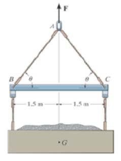
The lift sling is used to hoist a container having a mass of 500 kg. Determine the force in each of the cables AB and AC as a function of θ. If the maximum tension allowed in each cable is 5 kN, determine the shortest length of cobles AB end AC that can be used for the lift. The center of gravity of the container is located at G.
Prob. 3–12
The force in each of the cables AB and AC as a function of
The shortest length of cables AB and AC, which is used for the lift.
Answer to Problem 12P
The force in each of the cables AB and AC as a function of
The shortest length of cables AB and AC which is used for the lift (l) is
Explanation of Solution
Given information:
- The mass of the lift sling is 500 kg.
- The maximum tension allowed in each cable is 5 kN.
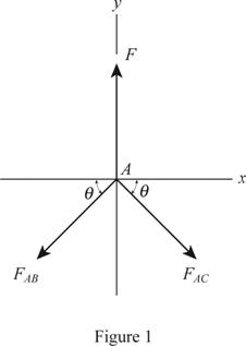
Show the free body diagram of the lift sling with the container as in Figure 1.
Observation:
The force F has to support the entire weight of the container.
Determine the weight of the lift sling.
Here, m is the mass of the lift sling and g is the acceleration due to gravity.
Determine the force in each of the cables AB and AC by applying the equation of equilibrium.
Along the horizontal direction:
Here, the force acting on cable AC is
Along the vertical direction:
Determine the shortest lengths of cables AB and AC using geometry.
Here, the length between the point B and G is
Formula used:
Conclusion:
Substitute 500 kg for m and
Substitute 4,905 N for F and F for
Determine the tension force angle using the formula.
Here, the maximum allowable tension force in the cable is F.
Substitute 5 kN for F.
Substitute 1.5 m for
Thus, the force in each of the cables AB and AC as a function of
Thus, the shortest length of cables AB and AC which is used for the lift is
Want to see more full solutions like this?
Chapter 3 Solutions
Engineering Mechanics: Statics & Dynamics (14th Edition)


- Q3 / The rectangular plate is supported by hinges along its side BC and by the cable AE. If the cable tension is 300 N, determine the projection onto line BC of the force exerted on the plate by the cable. Note that E is the midpoint of the horizontal upper edge of the structural support. Ans. Tec = 251 N C 400 mm D E 25 T= 300 N A 1200 mmarrow_forwardDetermine the Resultant of the forces acting on the T-BAR structure.arrow_forwardThe Engine Part has a weight of 400 N. Find components of this force (which is acting downward at point B) along members BA and BCarrow_forward
- The tower is held in place by three cables. If the force of each cable acting on the tower is shown, determine The coordinates of force vector FDAarrow_forwardThe backhoe and its contents have a combined weight of 300 kN and center of gravity at point G. Find the resulting force in cylinder AE and linkages AB and AD, indicating whether they are in Tension or Compression. Given: L1 = 300 mm, L2 = 75 mm, L3 = 450 mm, θ = 40 °, Φ = 60 °.arrow_forwardQ3 / The rectangular plate is supported by hinges along its side BC and by the cable AE. If the cable tension is 300 N, determine the projection onto line BC of the force exerted on the plate by the cable. Note that E is the midpoint of the horizontal upper edge of the structural support. Ans. Tec = 251 N C 400 mm 25° T= 300 N 1200 mm B Aarrow_forward
- The tube supports the four parallel forces. Determine the magnitudes of forces Fc and Fd acting at C and D so that the equivalent resultant force of the force system acts through the midpoint O of the tube.arrow_forwardThe horizontal boom carries the weight W=108lb at A. The boom is supported by the cables AB and AC. The tensions in the cables are TAB=120lb and TAC=160lb. Determine the single force R that is equivalent to three forces acting on the boom at A.arrow_forwardDraw the Free-Body Diagram if the weight acts on point Garrow_forward
- Determine the internal forces at point J of the structurearrow_forwardDetermine the resultant force and specify where it 2. acts on the beam measured from A. Also determine the reactions at A & B. 150 lb/ft B - 6 ft -8 ftarrow_forward3-90. The weights of the various components of the truck are shown. Replace this system of forces by an equivalent resultant force and specify its location measured from B. 175KN 27.5 kN V8.75 kN 4.2m -1.8 m- 0.6 m 0.9 marrow_forward
 International Edition---engineering Mechanics: St...Mechanical EngineeringISBN:9781305501607Author:Andrew Pytel And Jaan KiusalaasPublisher:CENGAGE L