
Videos
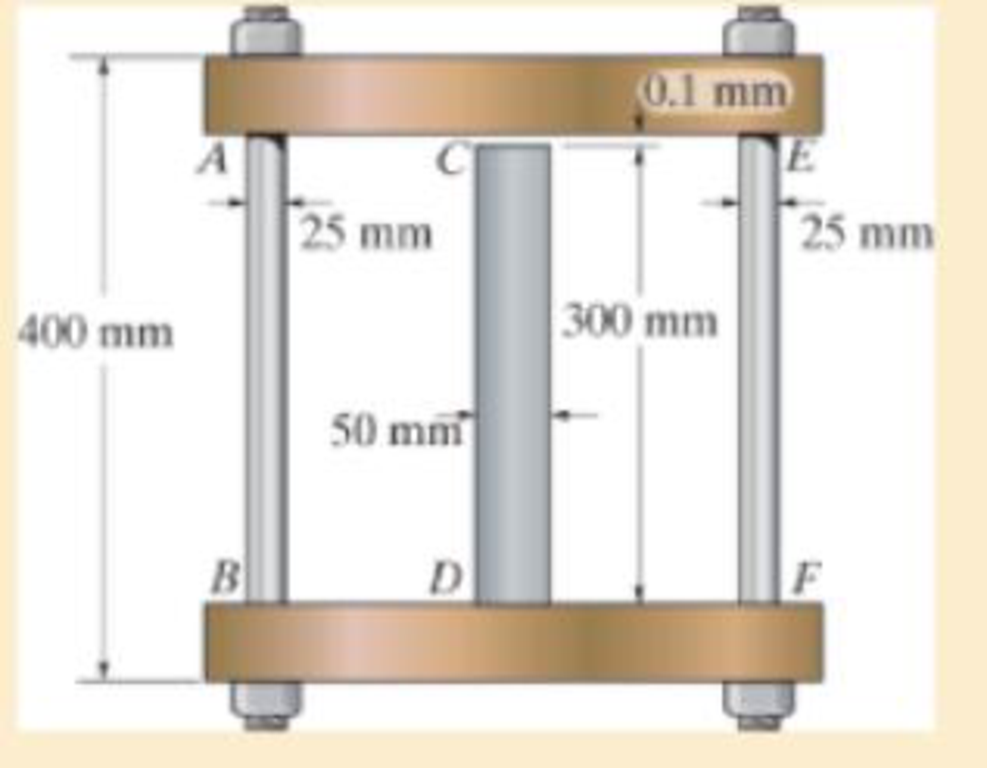
The assembly consists of two A992 steel bolts AB and EF and an 6061-T6 aluminum rod CD. When the temperature is at 30° C, the gap between the rod and rigid member AE is 0.1 mm Determine the normal stress developed in the bolts and the rod if the temperature rises to 130° C.
Assume BF is also rigid.
R4–1/2
The normal stress developed in the bolts and rod.
Answer to Problem 4.1RP
The normal stress developed in the bolts and rod are
Explanation of Solution
Given information:
The two bolts AB and EF are made of A992 steel.
The rod CD is made of 6061-T6 aluminum.
The Young’s modulus of the steel is
The Young’s modulus of the aluminum
The coefficient of thermal expansion of the steel
The coefficient of thermal expansion of the aluminum
The initial temperature
The finial temperature
The gap between the rod and rigid member AE is
The diameter of the bolts AB and EF
The diameter of the rod CD
The length of the bolts AB and EF
The length of the rod CD
Calculation:
Calculate the area of the bolts AB and EF
Substitute
Calculate the area of the rod CD
Substitute
Calculate the difference of temperature
Substitute
Show the free body diagram of the rigid cap as in Figure 1.
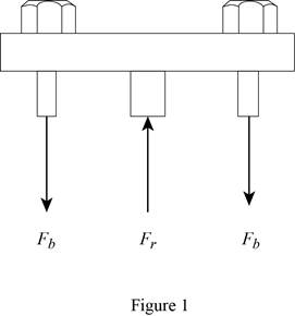
Refer Figure 1.
Calculate the vertical forces by applying the equation of equilibrium:
Sum of vertical forces is equal to 0.
Here,
Show the initial and final position of the assembly as in Figure 2.
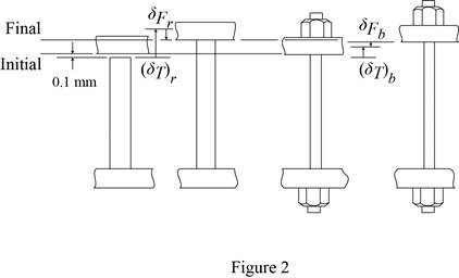
Refer Figure 2.
Here
The deformation is as follows:
Substitute
Calculate the force at the bolts AB and EF
Substitute
Calculate the force at the rod CD
Substitute
Calculate the normal stress developed in the bolts AB and EF
Substitute
Calculate the normal stress developed in the rod CD
Substitute
Hence, the normal stress developed in the bolts and rod are
Want to see more full solutions like this?
Chapter 4 Solutions
Mechanics of Materials (10th Edition)
Additional Engineering Textbook Solutions
Automotive Technology: Principles, Diagnosis, And Service (6th Edition) (halderman Automotive Series)
INTERNATIONAL EDITION---Engineering Mechanics: Statics, 14th edition (SI unit)
Applied Fluid Mechanics (7th Edition)
Thinking Like an Engineer: An Active Learning Approach (3rd Edition)
Thinking Like an Engineer: An Active Learning Approach (4th Edition)
Statics and Mechanics of Materials (5th Edition)


- The assembly consists of two A992 steel bolts AB and EF and an 6061-T6 aluminum rod CD. When the temperature is at 30° C, the gap between the rod and rigid member AE is 0.1 mm. Determine the normal stress developed in the bolts and the rod if the temperature rises to 130° C. Assume BF is also rigid.arrow_forwardThe bell-crank mechanism is in equilibrium for an applied load of F1 = 10 kN applied at A. Assume a = 260mm, b = 170mm, c = 70mm, and 0 = 40°. Pin B is in a double-shear connection and has a diameter of 20 mm. The bell crank has a thickness of 28 mm. Determine (a) the shear stress in pin B. (b) the bearing stress in the bell crank at B. Bell crank F2 Support bracket B A a b Farrow_forwardThe bell-crank mechanism is in equilibrium for an applied load of F₁ = 11 kN applied at A. Assume a = 320mm, b = 170mm, c = 85mm, and 0 = 40%. Pin B is in a double-shear connection and has a diameter of 29 mm. The bell crank has a thickness of 23 mm. Determine (a) the shear stress in pin B. (b) the bearing stress in the bell crank at B. Bell crank F₂ Support bracket b MPa Answers: Tpin B = i Ob= i a MPaarrow_forward
- 4-69. The assembly has the diameters and material make- up indicated. If it fits securely between its fixed supports when the temperature is T = 20°C, determine the average normal stress in each material when the temperature reaches T2= 40°C. 304 Stainless steel 2014-T6 Aluminum C 86100 Bronze A 300 mm 200 mm D. Cj100 'mm -1.2 m- 2 marrow_forwardThe bell-crank mechanism is in equilibrium for an applied load of F₁ = 13 kN applied at A. Assume a = 300mm, b = 140mm, c = 85mm, and 0 = 45° Pin B is in a double-shear connection and has a diameter of 34 mm. The bell crank has a thickness of 25 mm. Determine (a) the shear stress in pin B. (b) the bearing stress in the bell crank at B. Bell crank F₂ Support bracket Answers: Tpin B = i Ob= i 5 a B b MPa MPaarrow_forwardThe d - 15-mm-diameter solid rod passes through a D=20-mm-diameter hole in the support plate. When a load P is applied to the rod, the rod head rests on the support plate. The support plate has a thickness of b- 13 mm. The rod head has a diameter of a = 30 mm, and the head has a thickness of t= 10 mm. The shear stress in the rod head cannot exceed 130 MPa, the punching shear stress in the support plate cannot exceed 90 MPa, and the bearing stress between the rod head and the support plate cannot exceed 140 MPa. Determine the maximum value of Pmax that can be supported by the structure. Support Plate Rod Answer: Pmax i -Hole diameter D Head kN امarrow_forward
- The d = 15-mm-diameter solid rod passes through a D = 20-mm-diameter hole in the support plate. When a load P is applied to the rod, the rod head rests on the support plate. The support plate has a thickness of b = 15 mm. The rod head has a diameter of a = 30 mm, and the head has a thickness of t = 9 mm. If the normal stress produced in the rod by load P is 200 MPa, determine (a) the bearing stress acting between the support plate and the rod head. (b) the average shear stress produced in the rod head. (c) the punching shear stress produced in the support plate by the rod head. Support Plate Hole diameter D Rod Head Calculate the cross-sectional area of the rod. Answer: Arodi mm²arrow_forwardThe bell-crank mechanism is in equilibrium for an applied load of F1 = 11 kN applied at A. Assume a = 250mm, b = 100mm, c = 90mm, and θ = 40°. Pin B is in a double-shear connection and has a diameter of 29 mm. The bell crank has a thickness of 31 mm. Determine the shear stress in pin B. and the the bearing stress in the bell crank at B.arrow_forwardThe d = 16-mm-diameter solid rod passes through a D = 21-mm-diameter hole in the support plate. When a load P is applied to the rod, the rod head rests on the support plate. The support plate has a thickness of b = 10 mm. The rod head has a diameter of a = 32 mm, and the head has a thickness of t = 10 mm. The shear stress in the rod head cannot exceed 135 MPa, the punching shear stress in the support plate cannot exceed 80 MPa, and the bearing stress between the rod head and the support plate cannot exceed 155 MPa. Determine the maximum value of Pmax that can be supported by the structure. Support Plate Rod Answer: Pmax= i Hole diameter D Head kN aarrow_forward
- The bell-crank mechanism is in equilibrium for an applied load of F1 = 17 kN applied at A. Assume a = 290mm, b = 120mm, c = 80mm, and e = 35°. Pin B is in a double-shear connection and has a diameter of 33 mm. The bell crank has a thickness of 36 mm. Determine (a) the shear stress in pin B. (b) the bearing stress in the bell crank at B. Bell crank F2 Support bracket A a Answers: Tpin B = MPa Ob = i MPaarrow_forwardThe d = 15-mm-diameter solid rod passes through a D = 20-mm-diameter hole in the support plate. When a load P is applied to the rod, the rod head rests on the support plate. The support plate has a thickness of b = 10 mm. The rod head has a diameter of a = 30 mm, and the head has a thickness of t = 11 mm. The shear stress in the rod head cannot exceed 140 MPa, the punching shear stress in the support plate cannot exceed 105 MPa, and the bearing stress between the rod head and the support plate cannot exceed 130 MPa. Determine the maximum value of Pmax that can be supported by the structure. Support Plate Hole diameter D t Rod Answer: Pmax Mi -0 Head KN b→ aarrow_forwardThe d = 13-mm-diameter solid rod passes through a D=21-mm-diameter hole in the support plate. When a load P is applied to the rod, the rod head rests on the support plate. The support plate has a thickness of b = 12 mm. The rod head has a diameter of a = 28 mm, and the head has a thickness of t = 8 mm. If the normal stress produced in the rod by load P is 150 MPa, determine (a) the bearing stress acting between the support plate and the rod head. (b) the average shear stress produced in the rod head. (c) the punching shear stress produced in the support plate by the rod head. Support Plate Hole diameter D Rod Head b Calculate the cross-sectional area of the rod. Answer: Arod mm²arrow_forward
 Elements Of ElectromagneticsMechanical EngineeringISBN:9780190698614Author:Sadiku, Matthew N. O.Publisher:Oxford University Press
 Mechanics of Materials (10th Edition)Mechanical EngineeringISBN:9780134319650Author:Russell C. HibbelerPublisher:PEARSON
 Thermodynamics: An Engineering ApproachMechanical EngineeringISBN:9781259822674Author:Yunus A. Cengel Dr., Michael A. BolesPublisher:McGraw-Hill Education
 Control Systems EngineeringMechanical EngineeringISBN:9781118170519Author:Norman S. NisePublisher:WILEY
 Mechanics of Materials (MindTap Course List)Mechanical EngineeringISBN:9781337093347Author:Barry J. Goodno, James M. GerePublisher:Cengage Learning
 Engineering Mechanics: StaticsMechanical EngineeringISBN:9781118807330Author:James L. Meriam, L. G. Kraige, J. N. BoltonPublisher:WILEY