
Mechanics of Materials (10th Edition)
10th Edition
ISBN: 9780134319650
Author: Russell C. Hibbeler
Publisher: PEARSON
expand_more
expand_more
format_list_bulleted
Videos
Textbook Question
Chapter 4.2, Problem 4.1PP
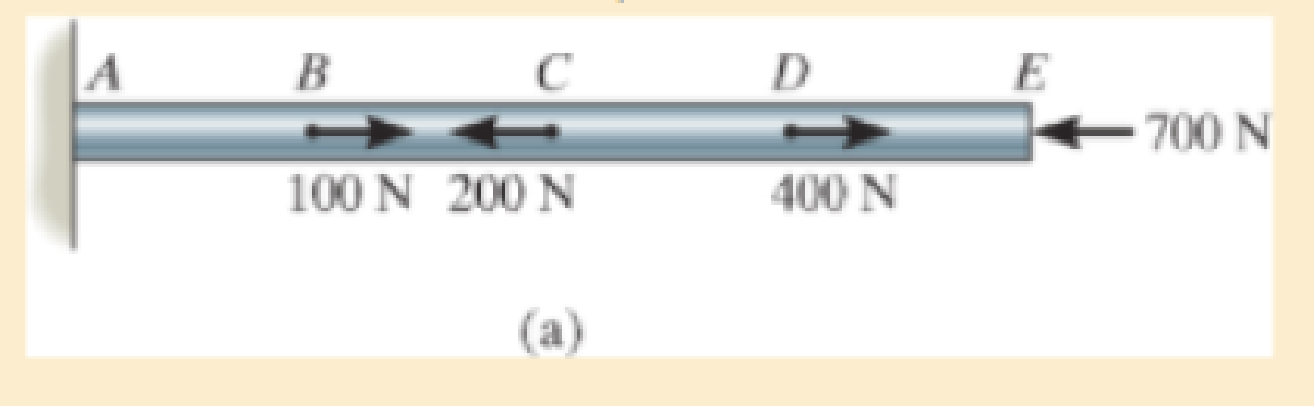
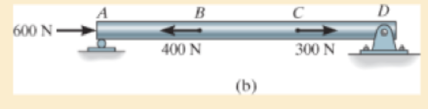
In each case, determine the internal normal force between lettered points on the bar. Draw all necessary free-body diagrams.
Expert Solution & Answer

Learn your wayIncludes step-by-step video

schedule03:59
Students have asked these similar questions
Given the figure determine the bar force at BD and AB
Determine the internal normal force between lettered points on the cable and rod. Draw all necessary free-body diagrams.
Compute the absolute internal force for the member
of CD. Consider P = 251 kN.
Chapter 4 Solutions
Mechanics of Materials (10th Edition)
Ch. 4.2 - In each case, determine the internal normal force...Ch. 4.2 - Determine the internal normal force between...Ch. 4.2 - The post weighs 8kN/m. Determine the internal...Ch. 4.2 - The rod is subjected to an external axial force of...Ch. 4.2 - The rigid beam supports the load of 60 kN....Ch. 4.2 - The 20-mm-diameter A-36 steel rod is subjected to...Ch. 4.2 - Segments AB and CD of the assembly are solid...Ch. 4.2 - The 30-mm-diameter A992 steel rod is subjected to...Ch. 4.2 - If the 20-mm-diameter rod is made of A-36 steel...Ch. 4.2 - The 20-mm-diameter 2014-T6 aluminum rod is...
Ch. 4.2 - The 20-mm-diameter 2014-T6 aluminum rod is...Ch. 4.2 - The A992 steel rod is subjected to the loading...Ch. 4.2 - The copper shaft is subjected to the axial loads...Ch. 4.2 - The composite shaft, consisting of aluminum,...Ch. 4.2 - The composite shaft, consisting of aluminum,...Ch. 4.2 - The 2014-T6 aluminium rod has a diameter of 30 mm...Ch. 4.2 - The A-36 steel drill shaft of an oil well extends...Ch. 4.2 - The truss is made of three A-36 steel members,...Ch. 4.2 - The truss is made of three A-36 steel members,...Ch. 4.2 - The assembly consists of two 10-mm diameter red...Ch. 4.2 - The assembly consists of two 10-mm diameter red...Ch. 4.2 - The load is supported by the four 304 stainless...Ch. 4.2 - The load is supported by the four 304 stainless...Ch. 4.2 - The rigid bar is supported by the pin-connected...Ch. 4.2 - The post is made of Douglas fir and has a diameter...Ch. 4.2 - The post is made of Douglas fir and has a diameter...Ch. 4.2 - The coupling rod is subjected to a force of 5 kip....Ch. 4.2 - The pipe is stuck in the ground so that when it is...Ch. 4.2 - The is made of three pin-connected A992 steel...Ch. 4.2 - The linkage is made of three pin connected A992...Ch. 4.2 - The assembly consists of three titanium...Ch. 4.2 - The rigid beam is supported at its ends by two...Ch. 4.2 - The rigid beam is supported at its ends by two...Ch. 4.2 - The steel bar has the original dimensions shown in...Ch. 4.2 - Determine the relative displacement of one end of...Ch. 4.2 - The assembly consists of two rigid bars that are...Ch. 4.2 - The truss consists of three members, each made...Ch. 4.2 - Solve Prob. 426 when the load P acts vertically...Ch. 4.2 - The observation cage C has a weight of 250 kip and...Ch. 4.2 - The steel bar has the original dimensions shown in...Ch. 4.2 - The ball is truncated at its ends and is used to...Ch. 4.5 - The column is constructed from high-strength...Ch. 4.5 - The column is constructed from high-strength...Ch. 4.5 - The A-36 steel pipe has a 6061-T6 aluminum core....Ch. 4.5 - If column AB is made from high strength precast...Ch. 4.5 - If column AB is made from high strength precast...Ch. 4.5 - Determine the support reactions at the rigid...Ch. 4.5 - If the supports at A and C are flexible and have a...Ch. 4.5 - The load of 2000 lb is to be supported by the two...Ch. 4.5 - The load of 2000 lb is to be supported by the two...Ch. 4.5 - The A-36 steel pipe has an outer radius of 20 mm...Ch. 4.5 - The 10-mm-diameter steel bolt is surrounded by a...Ch. 4.5 - The 10-mm-diameter steel bolt is surrounded by a...Ch. 4.5 - The assembly consists of two red brass C83400...Ch. 4.5 - The rigid beam is supported by the three suspender...Ch. 4.5 - The bolt AB has a diameter of 20 mm and passes...Ch. 4.5 - If the gap between C and the rigid wall at D is...Ch. 4.5 - The support consists of a solid red brass C83400...Ch. 4.5 - If there are n fibers, each having a...Ch. 4.5 - The rigid bar is pinned at A and supported by two...Ch. 4.5 - The rigid bar is pinned at A and supported by two...Ch. 4.5 - The rigid bar is pinned at A and supported by two...Ch. 4.5 - The rigid bar is pinned at A and supported by two...Ch. 4.5 - The 2014-T6 aluminum rod AC is reinforced with the...Ch. 4.5 - The 2014-T6 aluminum rod AC is reinforced with the...Ch. 4.5 - The three suspender bars are made of A992 steel...Ch. 4.5 - The three A-36 steel wires each have a diameter of...Ch. 4.5 - The A-36 steel wires AB and AD each have a...Ch. 4.5 - The post is made from 6061-T6 aluminum and has a...Ch. 4.5 - The post is made from 6061-T6 aluminum and has a...Ch. 4.5 - The bracket is held to the wall using three A-36...Ch. 4.5 - The bracket is held to the wall using three A-36...Ch. 4.5 - If each of the posts has an unloaded length of 1 m...Ch. 4.5 - The rigid bar is supported by the two short white...Ch. 4.5 - The assembly consists of two posts AB and CD each...Ch. 4.5 - The assembly consists of two posts AB and CD each...Ch. 4.5 - The assembly consists of two posts AB and CD each...Ch. 4.5 - The wheel is subjected to a force of 18 kN from...Ch. 4.6 - The C83400-red-brass rod AB and 2014-T6- aluminum...Ch. 4.6 - The assembly has the diameters and material...Ch. 4.6 - The rod is made of A992 steel and has a diameter...Ch. 4.6 - The two cylindrical rod segments are fixed to the...Ch. 4.6 - The two cylindrical rod segments are fixed to the...Ch. 4.6 - The pipe is made of A992 steel and is connected to...Ch. 4.6 - The bronze C86100 pipe has an inner radius of 0.5...Ch. 4.6 - The 40-ft-long A-36 steel rails on a train track...Ch. 4.6 - The device is used to measure a change in...Ch. 4.6 - The bar has a cross-sectional area A, length L,...Ch. 4.6 - When the temperature is at 30C, the A-36 steel...Ch. 4.6 - When the temperature is at 30C, the A-36 steel...Ch. 4.6 - When the temperature is at 30C, the A-36 steel...Ch. 4.6 - The 50-mm-diameter cylinder is made from Am...Ch. 4.6 - The 50-mm-diameter cylinder is made from Am...Ch. 4.6 - The wires AB and AC are made of steel, and wire AD...Ch. 4.6 - The cylinder CD of the assembly is heated from T1...Ch. 4.6 - The cylinder CD of the assembly is heated from T1=...Ch. 4.6 - The metal strap has a thickness t and width w and...Ch. 4.9 - Determine the maximum normal stress developed in...Ch. 4.9 - If the allowable normal stress for the bar is...Ch. 4.9 - The steel bar has the dimensions shown. Determine...Ch. 4.9 - The A-36 steel plate has a thickness of 12 mm. If...Ch. 4.9 - Determine the maximum axial force P that can be...Ch. 4.9 - Determine the maximum normal stress developed in...Ch. 4.9 - The member is to be made from a steel plate that...Ch. 4.9 - The resulting stress distribution along section AB...Ch. 4.9 - The resulting stress distribution along section AB...Ch. 4.9 - Prob. 4.96PCh. 4.9 - The weight is suspended from steel and aluminum...Ch. 4.9 - The bar has a cross-sectional area of 0.5 in2 and...Ch. 4.9 - The distributed loading is applied to the rigid...Ch. 4.9 - The distributed loading is applied to the rigid...Ch. 4.9 - The rigid lever arm is supported by two A-36 steel...Ch. 4.9 - The rigid lever arm is supported by two A-36 steel...Ch. 4.9 - The 300-kip weight is slowly set on the top of a...Ch. 4.9 - The rigid beam is supported by three 25-mm...Ch. 4.9 - The rigid beam is supported by three 25-mm...Ch. 4.9 - The rigid beam is supported by the three posts A,...Ch. 4.9 - The rigid beam is supported by the three posts A,...Ch. 4.9 - The bar having a diameter of 2 in. is fixed...Ch. 4.9 - Determine the elongation of the bar in Prob.4108...Ch. 4.9 - The rigid beam is supported by three A-36 steel...Ch. 4 - The assembly consists of two A992 steel bolts AB...Ch. 4 - The assembly shown consists of two A992 steel...Ch. 4 - The rods each have the same 25-mm diameter and...Ch. 4 - Two A992 steel pipes, each having a...Ch. 4 - The force P is applied to the bar, which is made...Ch. 4 - The 2014-T6 aluminum rod has a diameter of 0.5 in....Ch. 4 - The 2014-T6 aluminum rod has a diameter of 0.5 in....Ch. 4 - The rigid link is supported by a pin at A and two...Ch. 4 - The joint is made from three A992 steel plates...
Additional Engineering Textbook Solutions
Find more solutions based on key concepts
The force in each member of truss and the state of members are in Tension or Compression.
Engineering Mechanics: Statics & Dynamics (14th Edition)
Determine the velocity of block D if end A of the rope is pulled down with a speed of vA = 3 m/s.
Engineering Mechanics: Dynamics (14th Edition)
Determine the support reactions at the smooth journal bearings A, B, and C of the pipe assembly. Prob. F5-10
Engineering Mechanics: Statics
Replace the loading by an equivalent resultant force and couple moment acting at point A.
INTERNATIONAL EDITION---Engineering Mechanics: Statics, 14th edition (SI unit)
What parts are included in the vehicle chassis?
Automotive Technology: Principles, Diagnosis, And Service (6th Edition) (halderman Automotive Series)
What parts are included in the vehicle chassis?
Automotive Technology: Principles, Diagnosis, and Service (5th Edition)
Knowledge Booster


Learn more about
Need a deep-dive on the concept behind this application? Look no further. Learn more about this topic, mechanical-engineering and related others by exploring similar questions and additional content below.Similar questions
- Statics of Rigid Bodies (Round off to two (2) decimal places. Include negative sign (-) if the answer is negative.) The 13 kips force F acting on the simply supported beam. Determine the y component of F?arrow_forwardplz help before -ront The shaft is supported at its ends by two bearings A and B and is subjected to the forces applied to the pulleys fixed to the shaft. (Figure 1) The T₁ 410-N forces act in the - direction and the 200-N and 80-N forces act in the +y direction. The journal bearings at A and B exert only y and components of force on the shaft. Figure lashel but sol is 300 mm A 200 mm 2 150 mm 150 mm ✓ 200 mm 400 mm B. 200 N 200 N 80 N 80 N 1 of 1 ▾ Part B Determine the resultant shear force in the y direction on the cross section at C Express your answer to three significant figures and include appropriate units. (Vc)y=245.714 Submit Part C Submit * Incorrect; Try Again; 3 attempts remaining Check your signs. (Vc),= 175 ▾ Part D Determine the resultant shear force in the direction on the cross section at C. Express your answer to three significant figures and include appropriate unite. T= 10 ▾ Part E Previous Answere (Mc) Submit M ^ Part Fi * Incorrect; Try Again; 5 attempts remaining…arrow_forwardwith the following modifications: Add an additional force P = 20kN acting downwards at point Barrow_forward
- Show a free body diagram of the left section. Find the forces in the members listed by the Method of Sections. 1. Find forces in BD, BE and CE. (T C) BD = BE = (T C) CE = (T C) 1200 1800 540 5' A 12 12' 12' 540 2075 1675 300 450 B0arrow_forwardUse the method of sections to find the true magnitude and direction in bar DB of the truss. Hint (Joint C is in equilibrium)arrow_forwardThe two steel shafts (1) and (2) each Ø10 should be connected to each other with the help of the sleeve (3) (Øinner = 10, Øoutside = 15) also made of steel and two rivets at the points shown. The shaft (1) is firmly clamped on the left- hand side, the force F = 100 N acts on shaft 2 in the direction of the arrow. How are the brass round rivets to be dimensioned so that a safety of the coupling against failure of S = 10 is achieved? hole for rivets 1 F 3 a) What type of connection does a riveted connection have? b) What type of load does the rivet have? c) What is the diameter of the rivets? d) Which areas of the rivet are loaded? (Draw in figure and formula) e) Dimension the rivetarrow_forward
- Select F1=108 and F2=112 on the train bridge in the figure. Find the force on the bar BC and whether it is the pull.arrow_forwardSolve with complete Free Body Diagram.arrow_forwardPROBLEM 3. The aluminum rod has a solid circular cross-section and supports the loading shown. Drawing the normal force diagram and keeping the weight minimum, determine the diameter of the rod at each segment AB, BC, CD and DE. Compare the weight of the rod if the magnesium alloy AZ91D was used as the rod material. 8 kN E 4 kN 6 kN 2 kN 4 m -2 m- 2m-2 m-arrow_forward
- The system is made up of a bar, supported by a pin at point A and by a smooth collar at point B (the collar slides on the ABG bar). The collar is pinned to bar BDE, and bar BDE is supported by a pin at D and a cable at end E. Draw the bar BDR horizontaly and generate the cutting force diagram, flexing moment,show the max values of cutting force and flexing moment and its position . With T=26lb, a=4 in, b=9 inarrow_forwardProblem: The steel pipe has an inner diameter of 2.75 in and an outer diameter of 3 in. The pipe is fixed to the ground at C, and a wrench is attached to the opposite end. The wrench is subjected to a horizontal force of 20 lb that acts in -z direction. Points A and B are located on the surface of the pipe at the same cross section. Note that A lies directly above the -y axis, and B lies directly above the +z axis. 20 lb 10 in. A B y 12 in. (a) Find the normal and shear stresses at points A and B. (b) Find the principal stresses at points A and B. (c) Show all stresses from parts (a) and (b) on properly oriented elements, relative to the given coordinate system.arrow_forwardIn the following armor find the forces in the members CD, KD and JK of section 1-1 indicated in the figure.arrow_forward
arrow_back_ios
SEE MORE QUESTIONS
arrow_forward_ios
Recommended textbooks for you
 Elements Of ElectromagneticsMechanical EngineeringISBN:9780190698614Author:Sadiku, Matthew N. O.Publisher:Oxford University Press
 Mechanics of Materials (10th Edition)Mechanical EngineeringISBN:9780134319650Author:Russell C. HibbelerPublisher:PEARSON
 Thermodynamics: An Engineering ApproachMechanical EngineeringISBN:9781259822674Author:Yunus A. Cengel Dr., Michael A. BolesPublisher:McGraw-Hill Education
 Control Systems EngineeringMechanical EngineeringISBN:9781118170519Author:Norman S. NisePublisher:WILEY
 Mechanics of Materials (MindTap Course List)Mechanical EngineeringISBN:9781337093347Author:Barry J. Goodno, James M. GerePublisher:Cengage Learning
 Engineering Mechanics: StaticsMechanical EngineeringISBN:9781118807330Author:James L. Meriam, L. G. Kraige, J. N. BoltonPublisher:WILEY
Elements Of Electromagnetics
Mechanical Engineering
ISBN:9780190698614
Author:Sadiku, Matthew N. O.
Publisher:Oxford University Press
Mechanics of Materials (10th Edition)
Mechanical Engineering
ISBN:9780134319650
Author:Russell C. Hibbeler
Publisher:PEARSON
Thermodynamics: An Engineering Approach
Mechanical Engineering
ISBN:9781259822674
Author:Yunus A. Cengel Dr., Michael A. Boles
Publisher:McGraw-Hill Education
Control Systems Engineering
Mechanical Engineering
ISBN:9781118170519
Author:Norman S. Nise
Publisher:WILEY
Mechanics of Materials (MindTap Course List)
Mechanical Engineering
ISBN:9781337093347
Author:Barry J. Goodno, James M. Gere
Publisher:Cengage Learning
Engineering Mechanics: Statics
Mechanical Engineering
ISBN:9781118807330
Author:James L. Meriam, L. G. Kraige, J. N. Bolton
Publisher:WILEY
HOME SHOP JIGS & FIXTURES PART 1, TYPES OF JIGS & ACCESSORIES AND THE THEORIE BEHIND THE TOOLS; Author: THATLAZYMACHINIST;https://www.youtube.com/watch?v=EXYqi42JimI;License: Standard Youtube License