
Concept explainers
Videos
For the circuit in Fig. 8.58, the capacitor voltage at t = 0− (just before the switch is closed) is:
(a) 0 V
(b) 4 V
(c) 8 V
(d) 12 V
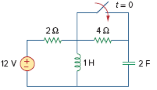
Figure 8.58
For Review Questions 8.1 and 8.2.
Choose the correct option to find the capacitor voltage at
Answer to Problem 1RQ
The correct option form the given choices is (a) 0 V.
Explanation of Solution
Calculation:
Redraw the given circuit as shown in Figure 1.
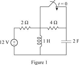
For the DC circuit, at the steady state condition when switch is open at
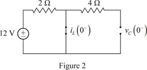
Since, the capacitor is open circuited, the voltage across the capacitor at
Therefore, the capacitor voltage at
Therefore, the option (a) is correct and the options (b), (c), (d) are incorrect.
Conclusion:
Thus, the correct option from the given choices is (a) 0 V.
Want to see more full solutions like this?
Chapter 8 Solutions
Fundamentals of Electric Circuits
Additional Engineering Textbook Solutions
Programmable Logic Controllers
Electric Circuits (10th Edition)
Engineering Electromagnetics
ELECTRICITY FOR TRADES (LOOSELEAF)
Electronics Fundamentals: Circuits, Devices & Applications
Principles and Applications of Electrical Engineering


- NOTE: Solve this as soon as possible, I need this urgently. For the circuit given below, show and explain what is the value of capacitor voltage before switch was closed. ww 12 V = 2Farrow_forward8. a). What are the values of the inductor voltage and current and the capacitor voltage and current assuming the switch has been closed for a very long time. VL= IL = Vc = Ic= 10 v 1H V₁ 000 502 HI 292 Ic↓ 1F Vcarrow_forward8.23 At t=0 s, a 100-V source is switched in series with a 1-k resistor and an uncharged 2-µF capacitor. What are (a) the initial capacitor voltage, (b) the initial current, (c) the initial rate of capacitor voltage increase, and (d) the time required for the capacitor voltage to reach its maximum value?arrow_forward
- The circuit shown below contains seven capacitors, each having capacitance C. The source voltage is given by v (1) = 4 cos(3t)V Find the current i(t) when C = 1 F. i(t) C v(t) C: C C C + Iarrow_forwardhow long it takes for a circuit with 30mH inductor and 8ohms resitor with a switch which connected as series to reach 85% of its maximum value. consider that at t=0 the switch is on the initial current is 0.arrow_forwardA series circuit has a capacitor of 0.25 x 10-0 F, a resistor of 5x 10' 2, and an inductor of 1 H. The initial charge on the capacitor is zero. If a 12-volt battery is connected to the ircuit and the circuit is closed at t = 0, determine the charge on the capacitor at t = 0.001 seconds, at t = 0.01 seconds, and at any time t. Also determine the limiting charge as - 0. Enter the exact answer with a < b. The charge at any time is given by the formula Q (1) = (Ae" + Beb + C) x 10-6 coulombs, where %3D x10-6 coulombs as t→ 0 tound your answers to two decimal places. 20 001) = x10-6 Coulomhsarrow_forward
- You are investigating the electrical testing circuits and find that, in an inductive circuit, the relationship between instantaneous current i (amps) and the time t (secs) is given by: i = 12.5(1-e-t/CR) You have been asked to determine the time taken for the current to rise from 1 to 2 amps given your own R and C values as follows. R= 140 C= 90arrow_forward(b) The voltage across a 4 N resistor of an RC circuit in Figure Q8(b) is given by VR (t) = 2e-6tu(t)V. Determine the total energy dissipated by this resistor using Parseval's Theorem. R C Figure Q8(b)arrow_forwardPlease use Nodal Analysis to solve this problem please. For the following circuit assume it has been in this state for a very long time . Determine the energy stored in the inductor and the capacitor Wl and Wcarrow_forward
- A resistance of (40Ω) , an inductance of (0.4H) and a capacitance of (150µF) are connected in series a cross (220V) ,(50Hz), the characteristics of the circuit is : capacitive inductance not any of the abovearrow_forward(b) A circuit network has two capacitors C1, and C2, that are connected in series and are supplied by a 12V voltage source. If C1 = 470µF and C2=220µF, sketch the circuit diagram and find the voltage across each of the capacitors:- (6) As a fresh engineer working with a mobile phone company, you have been tasked %3Darrow_forwardTRUE or FALSE a. A discontinuous change in the voltage requires an infinite current thus a capacitor resists an abrupt change in the voltage across it. b. The inductor takes power from the circuit when storing energy and delivers power to the circuit when returning previously stored energy.arrow_forward
 Introductory Circuit Analysis (13th Edition)Electrical EngineeringISBN:9780133923605Author:Robert L. BoylestadPublisher:PEARSON
 Delmar's Standard Textbook Of ElectricityElectrical EngineeringISBN:9781337900348Author:Stephen L. HermanPublisher:Cengage Learning
 Programmable Logic ControllersElectrical EngineeringISBN:9780073373843Author:Frank D. PetruzellaPublisher:McGraw-Hill Education
 Fundamentals of Electric CircuitsElectrical EngineeringISBN:9780078028229Author:Charles K Alexander, Matthew SadikuPublisher:McGraw-Hill Education
 Electric Circuits. (11th Edition)Electrical EngineeringISBN:9780134746968Author:James W. Nilsson, Susan RiedelPublisher:PEARSON
 Engineering ElectromagneticsElectrical EngineeringISBN:9780078028151Author:Hayt, William H. (william Hart), Jr, BUCK, John A.Publisher:Mcgraw-hill Education,