
Concept explainers
Videos
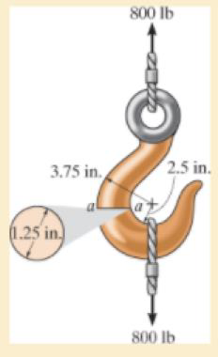
If it supports a cable loading of 800 lb, determine the maximum normal stress at section a–a and sketch the stress distribution acting over the cross section. Use the curved-beam formula to calculate the bending stress.
The maximum tensile stress
The maximum compressive stress
To sketch:
The stress distribution over the cross section.
Answer to Problem 8.1RP
The maximum tensile stress
The maximum compressive stress
Explanation of Solution
Given information:
The force in the cable is 800 lb.
Diameter of the circular is 1.25 in.
Calculation:
Expression to find the location of neutral
Here, R is the location of neutral axis, A is the cross sectional area of the member, r is the arbitrary position, and
Determine the radius
Here, d is the diameter of the circular cross section.
Substitute 1.25 in. for d in Equation (2).
Determine the area
Here, r is the radius of the circular cross section.
Substitute 0.625 in. for r in Equation (3).
Determine the value of
Here, c is the radius of cross section and
Find the distance measured from the center of curvature to the centroid of the cross section
Substitute 0.625 in. for c and 3.125 in. for
Substitute
Sketch the cross section of eye hook as shown in Figure 1.
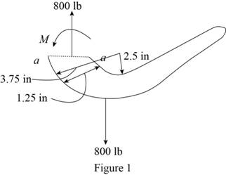
Let the moment acting at the section be M.
Express to the value of M as shown below:
Here, F is the load and R is the radius.
Determine the bending stress
Here, M is the applied moment and P is the applied load.
Substitute
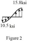
Determine the maximum tensile stress
Hence, the maximum tensile stress
Determine the maximum compressive stress
Substitute
Hence, the maximum compressive stress
Sketch the stress distribution (tensile and compressive stress) along the cross section as shown in Figure 2.
Want to see more full solutions like this?
Chapter 8 Solutions
Mechanics of Materials (10th Edition)


- The simply supported joist is used in the construction of a floor for a building. In order to keep the floor low with respect to the sill beams C and D, the ends of the joists are notched as shown. If the allowable shear stress is tallow = 350 psi and the allowable bending stress is sallow = 1500 psi, determine the height h that will cause the beam to reach both allowable stresses at the same time. Also, what load P causes this to happen? Neglect the stressconcentration at the notch.arrow_forwardThe handle of the press is subjected to a force of 20 lb. Due to internal gearing, this causes the block to be subjected to a compressive force of 80 lb. Determine the normal-stress acting in the frame at points along the outside flanges A and B. Use the curved-beam formula to calculate the bending stress.arrow_forwardIf the simply supported beam is subjected to the load shown below, determine the following: c- c - The internal bending moment acting on the cross-section through point C. d- d- The shear stress at section C.arrow_forward
- Determine the moment M that must be applied to the beam in order to create amaximum stress of 90 MPa. Also sketch the stress distribution acting over the cross section.arrow_forwardThe hook is subjected to the force of 80 lb. Determine the state of stress at point B at section a–a. The cross section has a diameter of 0.5 in. Use the curved-beam formula to calculate the bending stress.arrow_forwardThe wooden section of the beam is reinforced with two steel plates as shown. If the beam is subjected to a moment of M = 30 kN # m, determine the maximum bending stresses in the steel and wood. Sketch the stress distribution over the cross section. Take Ew = 10 GPa and Est = 200 GPa.arrow_forward
- The aluminium machine part shown below is subjected to a moment of M = 75 N.m. Determine the bending stress created at points B and A on the cross section. Sketch the results on a volume element located at each of these points. A- 50mm 50mm 100mm 100mm 20mm B- M=8kN-m 20mmarrow_forwardA member having the dimensions shown is used to resist an internal bending moment of M kNm. Determine the maximum stress in the member if the moment is applied (a) about the z axis (as shown) (b) about the y axis. Sketch the stress distribution for each case. Take: M= 90 kNm A mm A= 200 mm B= 150 mm B mm Solution: The moment of inertia of the cross-section about z and y axes are I;-4 1 - AB³ 12 (10) m* I BA = (10) m*arrow_forwardQ1/ A composite beam is made of wood and reinforced with steel strap located on its bottom side. It has the cross-sectional area shown in fig. if the beam is subjected to a bending moment of M=2kN.m, determine the normal stress at wood and steel. Take Ew=12Gpa and Est=200Gpa. 150mm Wood en 20mm Steel 150mmarrow_forward
- Below Figure shows the section of an angle purlin. A bending moment of 5 kN.m is applied to the purlin in a plane at an angle of 30 deg to the vertical y axis. If the sense of the bending moment is such that both its components Mx and My produce tension in the positive xy quadrant, calculate the maximum direct stress in the purlin, stating clearly the point at which it acts. * 100 mm E 10mm 30 C D -10mm 57 MPa. 89 MPa. Non Above O 72 MPa. 125mmarrow_forwardDetermine the internal normal force at point C, if F = 48 kN . Determine the shear force at point C Determine the bending moment at point Carrow_forwardGive the expression for the shear force, V = V(x), and the bending moment,M = M(x), as a function of the distance, x, measured from point A.Hint: Find the expressions of shear force and bending moment in each section:AB (0< x <4), BC (4 <x <7) and CD (7< x <10)arrow_forward
 Elements Of ElectromagneticsMechanical EngineeringISBN:9780190698614Author:Sadiku, Matthew N. O.Publisher:Oxford University Press
 Mechanics of Materials (10th Edition)Mechanical EngineeringISBN:9780134319650Author:Russell C. HibbelerPublisher:PEARSON
 Thermodynamics: An Engineering ApproachMechanical EngineeringISBN:9781259822674Author:Yunus A. Cengel Dr., Michael A. BolesPublisher:McGraw-Hill Education
 Control Systems EngineeringMechanical EngineeringISBN:9781118170519Author:Norman S. NisePublisher:WILEY
 Mechanics of Materials (MindTap Course List)Mechanical EngineeringISBN:9781337093347Author:Barry J. Goodno, James M. GerePublisher:Cengage Learning
 Engineering Mechanics: StaticsMechanical EngineeringISBN:9781118807330Author:James L. Meriam, L. G. Kraige, J. N. BoltonPublisher:WILEY