
Concept explainers
Videos
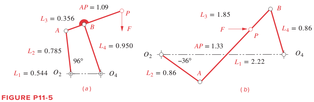
Figure P11-5a shows a fourbar linkage and its dimensions in meters. The steel crank, coupler, and rocker have uniform cross sections of 50 mm wide by 25 mm thick. In the instantaneous position shown, the crank
Problems 11-11 to 11-12
Want to see the full answer?
Check out a sample textbook solution
Chapter 11 Solutions
DESIGN OF MACHINERY


- Problem 4-6a The link lengths (a, b, c, d) and the value of 62 for a crank-rocker linkage are defined as 2, 7, 9, 6, 30°, respectively. Draw the scaled linkage. Find all possible solutions (both open and crossed) for angles 03 and 04 graphically. Open B 3 A LNCS 4 04 GCS O4 Crossed (This is not the scaled kinematic diagram.) Problem 4-7a Repeat Problem 4-6a except solve by the vector loop method.arrow_forwardProblem 2 The linkage in Figure P7-5b has o4A = o2A = 0.75, AB = 1.5, and AC = 1.2 in. The effective crank angle in the position shown is 77° and angle BAC = 30°. Find a3, AA, AB, Ac for the position shown for w2 = 15 rad/sec and a2 = 10 rad/sec^2 in the directions shown using an analytic method. (Hint: Create an effective linkage for the position shown and analyze it as a pin-jointed fourbar.) the linkage has a parallelogram form Assume rolling contactarrow_forwardFor the mechanism shown in figure. Obtain the angular velocity of link 3 and the slipping velocity between link 3 and link = 5 inches RAO 4 = 4 Using loop closure method. The lengths of links RPA 5î in/sec. LAPO = 90 degrees. 10 inches and VA = 0& TA r₂ 1 "arrow_forward
- Find the Grashof condition, any limit positions, and the extreme values of the transmission angle (to graphical accuracy) of the linkage in the following figure. AP = 0.97 L₂ = 0.72 02 54° L3 = 0.68 L₁ 1 1 = 1.82 B L4 = 0.85arrow_forwardA general pinjointed fourbar linkage is shown in the figure below. It has the followings: The link lengths are L1 = 8.50 in., L2 = 3.00 in., L3 = 5.00 in. and L4 = 4.50 in. The values of θ1 = 0, θ2 = 60°, and θ4 = 119°. The angular velocity of link2 ω2 = 10 rad/s CCW. The angular velocities of link 3 ω3 and and link 4 ω4 are: Select one: a. ω3 = 5.29 rad/s CW, ω4 = 4.80 rad/s CCW b. ω3 = 5.29rad/s CW, ω4 = 6.14 rad/s CW c. ω3 = 3.94 rad/s CCW, ω4 = 4.8 rad/s CCW d. ω3 = 3.94 rad/s CCW, ω4 = 6.14 rad/s CCWarrow_forwardProblem 2 The linkage in Figure P7-5b has O4A = O2A = 0.75, AB = 1.5, and AC = 1.2 in. The effective crank angle in the position shown is 77° and angle BAC = 30°. Find a3, AA. AB,Ac for the position shown for w2 = 15 rad/sec and a2 = 10 rad/sec^2 in the directions shown using an analytic method. (Hint: Create an effective linkage for the position shown and analyze it as a pin-jointed fourbar.)the linkage has a parallelogram form Assume rolling contactarrow_forward
- The link length and value of O2 for some four bar linkages are defined below, (fixed link =12 cm, drive link =5 cm, coupler link = 10 cm, follower link= 8 cm) 1. draw the linkage to scale and graphically find all possible solution (both open and cross) for 03 and O4, analytical . 2. If w = 2 rad /s (CCW) find the angular velocity for bar 3 and 4 3.if a= 5 rad/s² (CCW) find the normal and tangential acceleration for link 3 and 4arrow_forward1. Find a combination of link lengths where motion of a point on output link is one quarter of a circle. 2. Find the value of all 0, 0, 0, and y in open and close configuration Read the value of link lengths and the input angle 8., then use the formulae given below to calculate the value of unknowns 03, 0, and y K₁ = = K₂= d K2 K3 = a²-b²+c²+d² 2ac A = cos 0₂ - K₁ - K₂ cos 0₂ + K3 B = -2 sin 0₂ C = K₁ (K₂ + 1) cos 02 + K3 -B± √B²-4AC 2A 0412 = 2tan-1 d K₁ = — K5 = c²d²a²-6² 2ab D = cos 0₂ - K₁ - K4 cos 0₂ + K5 E = -2 sin 0₂ FK₁+ (K₁ - 1) cos 02 +K5 0312 2 tan-1 (-E± -E± √E²4DF 2D Y = 04-03arrow_forwardQestion-1: A slider-crank mechanism is shown in figure below. Position vectors for various linkages are drawn as shown in figure. Length of the rotating Link-1 (L1) is continuously changing due to the slider placed on it. Link-3 is fixed and aligned along y-axis. Note: All angles are measured anti-clockwise from x-axis and Link-1 is rotating with uniform velocity Take: L2 = 20mm, 02 =45°, L3= 30mm, o=10rad/sec, V2= 1000mm/s. a) Formulate the vector loop, position, velocity and acceleration equations b) Solve to find 01, L1, linear velocity of slider and angular acceleration of link-1. c) Identify if the mechanism can be declared as spatial or planar mechanism also identify total number of full and half joints.arrow_forward
- Problem 2 The linkage in Figure P7-5b has O,A = O2A = 0.75, AB= 1.5, and AC = 1.2 in. The effective crank angle in the position shown is 77° and angle BAC = 30°. Find a3, A4, AB,Ac for the position shown for @2 = 15 rad/sec and a2 = 10 rad/sec in the directions shown using an analytical method. (Hint: Create an effective linkage for the position shown and analyze it as a pin-jointed fourbar.)the linkage has a parallelogram form Assume rolling contact C @2 A 3 В a2 2 4 04arrow_forwardA general inverted fourbar slider-crank linkage has links length: link 2 = a = 2, link 4 = c = 4, and link 1= d = 6 in. The input values are 02 = 60°, y = 90°. The linkage configuration and terminology are shown in figure below; note that this figure does not represent the real dimensions of the linkage We need to find the angular positions of link 4 (04), of link 3 (03) and the effective length of link 3 (b) for both open and crossed configurations. 03 Өд В 4 RB 02 02 1 02 04 Choose... For open configuration, the angle 04 measured form X axis CCW in degree = Choose... For open configuration, the angle 03 measured form X axis CCW in degree = Choose... + For open configuration, the absolute value of the effective length of link 3, b = Choose... For crossed configuration, the angle 04 measured form X axis CCW in degree = Choose... For crossed configuration, the angle 03 measured form X axis CCW in degree = Choose... For crossed configuration, the absolute value of the effective length of…arrow_forwardA pinjointed fourbar linkage is shown in the figure below. The link lengths are L1 = 7.8 in., L2 = 2.9 in., L3 = 7.25 in. and L4= 3.5 in. Using the current position, 02-100°, the position analysis has determined that 04 = 214.25°. Currently, link 2 is traveling at 5.50 rad/s CCW Lep B. Figure 6.7 Four-bar linkage acceleration analysis The angular velocities of link 3 w3 and and link 4 Wa are: Select one: O a. w3 = 3.589 rad/s, Wa = -2.91 rad/s O b. w3 = 2.07rad/s, wa = -2.91 rad/s C. W3 = 2.7 rad/s, wa 3.428 rad/s O d. w3 = 2.07 rad/s, w4 = -3.38 rad/sarrow_forward
 Elements Of ElectromagneticsMechanical EngineeringISBN:9780190698614Author:Sadiku, Matthew N. O.Publisher:Oxford University Press
 Mechanics of Materials (10th Edition)Mechanical EngineeringISBN:9780134319650Author:Russell C. HibbelerPublisher:PEARSON
 Thermodynamics: An Engineering ApproachMechanical EngineeringISBN:9781259822674Author:Yunus A. Cengel Dr., Michael A. BolesPublisher:McGraw-Hill Education
 Control Systems EngineeringMechanical EngineeringISBN:9781118170519Author:Norman S. NisePublisher:WILEY
 Mechanics of Materials (MindTap Course List)Mechanical EngineeringISBN:9781337093347Author:Barry J. Goodno, James M. GerePublisher:Cengage Learning
 Engineering Mechanics: StaticsMechanical EngineeringISBN:9781118807330Author:James L. Meriam, L. G. Kraige, J. N. BoltonPublisher:WILEY