
Loose Leaf for Engineering Circuit Analysis Format: Loose-leaf
9th Edition
ISBN: 9781259989452
Author: Hayt
Publisher: Mcgraw Hill Publishers
expand_more
expand_more
format_list_bulleted
Concept explainers
Videos
Textbook Question
Chapter 5, Problem 76E
With respect to the circuit in Fig. 5.90, (a) employ Thévenin’s theorem to determine the equivalent network seen by resistor RL, (b) use source transformations to reduce the circuit to its Norton equivalent, and (c) compute the power delivered to RL if it is equal to half of the Thévenin equivalent resistance, using both circuits.
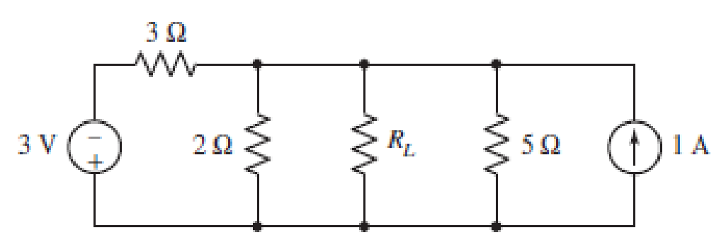
FIGURE 5.90
Expert Solution & Answer
Want to see the full answer?
Check out a sample textbook solution
Students have asked these similar questions
5.55
In the circuit of Fig. 5-54, what resistor R, will absorb maximum power, and what is this power!
Ans. 3.33 N. 480 W
CHAP. 5]
DC EQUIVALENT CIRCUITS, NETWORK THEOREMS
109
152
120 V
021,
R,
Fig. 5-54
Summary: Thevenin Equivalent Circult
For the circuit in Figure 5:
(a) Find the Open Circuit Voltage, voc, between terminals a and b by voltage division (do NOT use other methods)
(b) Use the Deactivation Method to find the Thevenin Equlvalent Resistance between terminals a and b
(c) Draw the Thevenin Equivalent Circuit with respect to terminals a and b.
Figure 5
10 2
12 2
a
15 V
15 Ω
9.
Using Kirchhoff's voltage law, find the unknown voltages
for the configurations in Fig. 5.107.
20 V
+ V₁ -
- IV +
+
10 V
ō
+2V-
www
www
- V₂ +
10 V
+ V₁ -
www
V₂
- 6V +
+|||
- 3V+
2 V
Chapter 5 Solutions
Loose Leaf for Engineering Circuit Analysis Format: Loose-leaf
Ch. 5.1 - For the circuit of Fig. 5.4, use superposition to...Ch. 5.2 - For the circuit of Fig. 5.7, use superposition to...Ch. 5.2 - For the circuit of Fig. 5.18, compute the current...Ch. 5.2 - For the circuit of Fig. 5.20, compute the voltage...Ch. 5.3 - Using repeated source transformations, determine...Ch. 5.3 - Use Thvenins theorem to find the current through...Ch. 5.3 - Determine the Thvenin and Norton equivalents of...Ch. 5.3 - Find the Thvenin equivalent for the network of...Ch. 5.3 - Find the Thvenin equivalent for the network of...Ch. 5.4 - Consider the circuit of Fig. 5.43. FIGURE 5.43...
Ch. 5.5 - Prob. 11PCh. 5 - Linear systems are so easy to work with that...Ch. 5 - Prob. 2ECh. 5 - Prob. 3ECh. 5 - (a) Employ superposition to determine the current...Ch. 5 - (a) Using superposition to consider each source...Ch. 5 - (a) Determine the individual contributions of each...Ch. 5 - (a) Determine the individual contributions of each...Ch. 5 - After studying the circuit of Fig. 5.53, change...Ch. 5 - Consider the three circuits shown in Fig. 5.54....Ch. 5 - (a) Using superposition, determine the voltage...Ch. 5 - Employ superposition principles to obtain a value...Ch. 5 - (a) Employ superposition to determine the...Ch. 5 - Perform an appropriate source transformation on...Ch. 5 - (a) For the circuit of Fig. 5.59, plot iL versus...Ch. 5 - Determine the current labeled I in the circuit of...Ch. 5 - Verify that the power absorbed by the 7 resistor...Ch. 5 - (a) Determine the current labeled i in the circuit...Ch. 5 - (a) Using repeated source transformations, reduce...Ch. 5 - Prob. 19ECh. 5 - (a) Making use of repeated source transformations,...Ch. 5 - Prob. 21ECh. 5 - (a) With the assistance of source transformations,...Ch. 5 - For the circuit in Fig. 5.67 transform all...Ch. 5 - Prob. 24ECh. 5 - (a) Referring to Fig. 5.69, determine the Thevenin...Ch. 5 - (a) With respect to the circuit depicted in Fig....Ch. 5 - (a) Obtain the Norton equivalent of the network...Ch. 5 - (a) Determine the Thevenin equivalent of the...Ch. 5 - Referring to the circuit of Fig. 5.71: (a)...Ch. 5 - Prob. 30ECh. 5 - (a) Employ Thvenins theorem to obtain a...Ch. 5 - Prob. 32ECh. 5 - Determine the Norton equivalent of the circuit...Ch. 5 - For the circuit of Fig. 5.75: (a) Employ Nortons...Ch. 5 - (a) Obtain a value for the Thvenin equivalent...Ch. 5 - Prob. 36ECh. 5 - Obtain a value for the Thvenin equivalent...Ch. 5 - With regard to the network depicted in Fig. 5.79,...Ch. 5 - Determine the Thvenin and Norton equivalents of...Ch. 5 - Determine the Norton equivalent of the circuit...Ch. 5 - Prob. 41ECh. 5 - Determine the Thvenin and Norton equivalents of...Ch. 5 - Prob. 43ECh. 5 - Prob. 44ECh. 5 - Prob. 45ECh. 5 - (a) For the simple circuit of Fig. 5.87, find the...Ch. 5 - For the circuit drawn in Fig. 5.88, (a) determine...Ch. 5 - Study the circuit of Fig. 5.89. (a) Determine the...Ch. 5 - Prob. 49ECh. 5 - Prob. 50ECh. 5 - With reference to the circuit of Fig. 5.91, (a)...Ch. 5 - Prob. 52ECh. 5 - Select a value for RL in Fig. 5.93 such that it...Ch. 5 - Determine what value of resistance would absorb...Ch. 5 - Derive the equations required to convert from a...Ch. 5 - Convert the - (or "-") connected networks in Fig....Ch. 5 - Convert the Y-(or T-) connected networks in Fig....Ch. 5 - For the network of Fig. 5.97, select a value of R...Ch. 5 - For the network of Fig. 5.98, select a value of R...Ch. 5 - Prob. 60ECh. 5 - Calculate Rin as indicated in Fig.5.100. FIGURE...Ch. 5 - Employ Y conversion techniques as appropriate to...Ch. 5 - Prob. 63ECh. 5 - (a) Use appropriate techniques to obtain both the...Ch. 5 - (a) For the network in Fig. 5.104, replace the...Ch. 5 - Prob. 66ECh. 5 - Prob. 67ECh. 5 - A 2.57 load is connected between terminals a and...Ch. 5 - A load resistor is connected across the open...Ch. 5 - A backup is required for the circuit depicted in...Ch. 5 - (a) Explain in general terms how source...Ch. 5 - The load resistor in Fig. 5.108 can safely...Ch. 5 - Prob. 74ECh. 5 - As part of a security system, a very thin 100 ...Ch. 5 - With respect to the circuit in Fig. 5.90, (a)...
Additional Engineering Textbook Solutions
Find more solutions based on key concepts
For the “tank” circuit in Fig. 14.79, find the resonant frequency.
Figure 14.79
For Probs. 14.39, 14.71, and 1...
Fundamentals of Electric Circuits
The current source in the circuit shown generates the current pulse
Find (a) v (0); (b) the instant of time gr...
Electric Circuits. (11th Edition)
Three point charges of equal magnitude q, that will yield a zero net electric field at the origin.
Engineering Electromagnetics
Assume a telephone signal travels through a cable at two-thirds the speed of light. How long does it take the s...
Electric Circuits (10th Edition)
Design an ideal inverting op-amp circuit such that the voltage gain is Av=25 . The maximum current in any resis...
Microelectronics: Circuit Analysis and Design
How many coulombs do 93.8 1016 electrons represent?
Principles Of Electric Circuits
Knowledge Booster


Learn more about
Need a deep-dive on the concept behind this application? Look no further. Learn more about this topic, electrical-engineering and related others by exploring similar questions and additional content below.Similar questions
- a. Design the circuit in Fig. 5.117 such that VR₂ = 3VR, and VR₂ 4 VR₂ b. If the current is reduced to 10 μA, what are the new val- ues of R₁, R₂, and R3? How do they compare to the re- sults of part (a)? AL- = إسكان E 10 mA 4₁₁ www www R₁ R₂ 64 V R3 wwwarrow_forwardUsing Kirchhoff's voltage law, find the unknown voltages for the configurations in Fig. 5.107. 20 V + V₁ - www www - IV + + 10 V ō + 2V www - V₂ + 10 V + + V₁ + www V₂ -6V+ +|₁| www - 3V + 2 Varrow_forwardHomework: Obtain vo in the circuit of the following figure. 5.3 30 V 20 V 4 kS2 2 k2 5 k2 Answer 20 Varrow_forward
- 5.40 Find the Norton equivalent of the circuit of Fig. 5-43. Reference I, up. Ans. 8 Ω.8Α 40 0 80 V 30 A 10 0 1000 V Fig. 5-43arrow_forward21/ Potential Divider Principle is the simplest way of producing a source of higher EMF from a source of lower EMF. Select one: True Falsearrow_forwardExample: 5.1 Calculate the node voltages in the circuit shown in the below figure: 5 A 42 21 22 10 Aarrow_forward
- Q5. (a) Perform mesh analysis to find the current i, in Figure Q5 (a). 6 V 10 12 v (+ Figure Q5 (a) (b) The following results were obtained from measurements taken between the two terminals of a resistive circuit network Condition 1 12 V O A Condition 2 Terminal Voltage Terminal Current OV 20 A (i) Draw the possible circuit based on the information provided above. If the circuit is connected to an electric bulb of resistance 2 N, determine the power dissipated by the bulb. (ii) wwarrow_forwardPractice: 5.3 Find v and i in the circuit in the below figure. 3 V 7 V 22 Answer: -0.2 V, 1.4 A. University of Thi-Qar/Department of Electrical and Electronic Engineering-Lectures are prepared by M.Sc. All Kareem Pagearrow_forwardProblem 5. Use superposition to design a circuit that allows fine and coarse voltages to be combined. Select resistor values R1, R2, and R that allow Vtune = 20 Vfine +Vcoarse Vcoarse R₁2 + REV R₂ tune V finearrow_forward
- Consider the given circuit where /x = 5.5 A. 7 V 392 2 A 30 I Using as many source transformations and element combination techniques as required, simplify the given circuit so that it contains only the 7 V source, a single resistor, and one other voltage source. (You must provide an answer before moving on to the next part.) The simplified circuit contains the 7 V source, a single resistor of Q, and another voltage source of V.arrow_forward106 DC EQUIVALENT CIRCUITS, NETWORK THEOREMS [CHAP. 5 5.41 Determine the Norton equivalent of the circuit of Fig. 5-44. Reference I up. Ans. 78 Q, 1.84 A 40 N 35 V 60 V 30 2 202 2 A 45 0 15 0 IS V Fig. 5-44arrow_forwardHomework: Obtain vo in the circuit of the following figure. 5.3 30 V 20 V 4 k2 2 kn 5 kn Answer 20 V www wwarrow_forward
arrow_back_ios
SEE MORE QUESTIONS
arrow_forward_ios
Recommended textbooks for you
 Introductory Circuit Analysis (13th Edition)Electrical EngineeringISBN:9780133923605Author:Robert L. BoylestadPublisher:PEARSON
 Delmar's Standard Textbook Of ElectricityElectrical EngineeringISBN:9781337900348Author:Stephen L. HermanPublisher:Cengage Learning
 Programmable Logic ControllersElectrical EngineeringISBN:9780073373843Author:Frank D. PetruzellaPublisher:McGraw-Hill Education
 Fundamentals of Electric CircuitsElectrical EngineeringISBN:9780078028229Author:Charles K Alexander, Matthew SadikuPublisher:McGraw-Hill Education
 Electric Circuits. (11th Edition)Electrical EngineeringISBN:9780134746968Author:James W. Nilsson, Susan RiedelPublisher:PEARSON
 Engineering ElectromagneticsElectrical EngineeringISBN:9780078028151Author:Hayt, William H. (william Hart), Jr, BUCK, John A.Publisher:Mcgraw-hill Education,
Introductory Circuit Analysis (13th Edition)
Electrical Engineering
ISBN:9780133923605
Author:Robert L. Boylestad
Publisher:PEARSON
Delmar's Standard Textbook Of Electricity
Electrical Engineering
ISBN:9781337900348
Author:Stephen L. Herman
Publisher:Cengage Learning
Programmable Logic Controllers
Electrical Engineering
ISBN:9780073373843
Author:Frank D. Petruzella
Publisher:McGraw-Hill Education
Fundamentals of Electric Circuits
Electrical Engineering
ISBN:9780078028229
Author:Charles K Alexander, Matthew Sadiku
Publisher:McGraw-Hill Education
Electric Circuits. (11th Edition)
Electrical Engineering
ISBN:9780134746968
Author:James W. Nilsson, Susan Riedel
Publisher:PEARSON
Engineering Electromagnetics
Electrical Engineering
ISBN:9780078028151
Author:Hayt, William H. (william Hart), Jr, BUCK, John A.
Publisher:Mcgraw-hill Education,
Z Parameters - Impedance Parameters; Author: Electrical Engineering Authority;https://www.youtube.com/watch?v=qoD4AoNmySA;License: Standard Youtube License