
Mechanics of Materials
9th Edition
ISBN: 9780133254426
Author: Russell C. Hibbeler
Publisher: Prentice Hall
expand_more
expand_more
format_list_bulleted
Videos
Textbook Question
Chapter 1, Problem 1.101RP
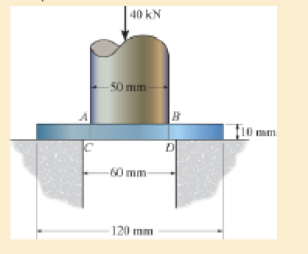
Determine the average punching shear stress the circular shaft creates in the metal plate through section AC and BD. Also, what is the average bearing stress developed on the surface of the plate under the shaft?
Expert Solution & Answer
Want to see the full answer?
Check out a sample textbook solution
Students have asked these similar questions
Determine the average normal stress developed at points A, B, and C. The diameter ofeach segment is indicated in the Figure below.
Determine the average punching shear stress the circular shaft creates in the metal plate throughsection AC and BD. Also, determine the average bearing stress developed on the surface of theplate under the shaft.
Determine the average punching shear stress the
| 40 kN
circular shaft creates in the metal plate through section AC
and BD. Also, what is the bearing stress developed on the
surface of the plate under the shaft?
50 mm
(10 mm
IC
D
60 mm
120 mm
Chapter 1 Solutions
Mechanics of Materials
Ch. 1.2 - In each case, explain how to find the resultant...Ch. 1.2 - Determine the resultant internal normal force,...Ch. 1.2 - Determine the resultant internal normal force,...Ch. 1.2 - Determine the resultant internal normal force,...Ch. 1.2 - Determine the resultant internal normal force,...Ch. 1.2 - Determine the resultant internal normal force,...Ch. 1.2 - Determine the resultant internal normal force,...Ch. 1.2 - The shaft is supported by a smooth thrust bearing...Ch. 1.2 - Determine the resultant internal normal and shear...Ch. 1.2 - 1-3. The beam AB is fixed to the wall and has a...
Ch. 1.2 - The shaft is supported by a smooth thrust bearing...Ch. 1.2 - 1-5. Determine the resultant internal loadings in...Ch. 1.2 - 1-6. Determine the normal force, shear force, and...Ch. 1.2 - 1-7. The cable will fail when subjected to a...Ch. 1.2 - *1-8. Determine the resultant internal loadings on...Ch. 1.2 - 1-9. Determine the resultant internal loadings on...Ch. 1.2 - The boom DF of the jib crane and the column DE...Ch. 1.2 - 1-11. The forearm and biceps support the 2-kg load...Ch. 1.2 - *1-12. The serving tray T used on an airplane is...Ch. 1.2 - The blade of the hacksaw is subjected to a...Ch. 1.2 - The blade of the hacksaw is subjected to a...Ch. 1.2 - 1-15. A 150-lb bucket is suspended from a cable on...Ch. 1.2 - *1-16. A 150-lb bucket is suspended from a cable...Ch. 1.2 - 1-17. Determine resultant internal loadings acting...Ch. 1.2 - Prob. 1.18PCh. 1.2 - Prob. 1.19PCh. 1.2 - Prob. 1.20PCh. 1.2 - Prob. 1.21PCh. 1.2 - The metal stud punch is subjected to a force of...Ch. 1.2 - Determine the resultant internal loadings acting...Ch. 1.2 - Prob. 1.24PCh. 1.2 - 1-25. Determine the resultant internal loading...Ch. 1.2 - 1-26. The shaft is supported at its ends by two...Ch. 1.2 - 1-27. The pipe assembly is subjected to a force of...Ch. 1.2 - If the drill bit jams when the brace is subjected...Ch. 1.2 - 1-29. The curved rod AD of radius r has a weight...Ch. 1.2 - A differential element taken from a curved bar is...Ch. 1.5 - In each case, determine the largest internal shear...Ch. 1.5 - Determine the largest internal normal force in the...Ch. 1.5 - Determine the internal normal force at section A...Ch. 1.5 - Prob. 1.5PPCh. 1.5 - The single-V butt joint transmits the force of 5...Ch. 1.5 - The uniform beam is supported by two rods AB and...Ch. 1.5 - Determine the average normal stress on the cross...Ch. 1.5 - Determine the average normal stress on the cross...Ch. 1.5 - If the 600-kN force acts through the centroid of...Ch. 1.5 - Determine the average normal stress at points A,...Ch. 1.5 - Determine the average normal stress in rod AB if...Ch. 1.5 - The supporting wheel on a scaffold is held in...Ch. 1.5 - Prob. 1.32PCh. 1.5 - The bar has a cross-sectional area A and is...Ch. 1.5 - 1-34. The built-up shaft consists of a pipe AB and...Ch. 1.5 - Prob. 1.35PCh. 1.5 - Prob. 1.36PCh. 1.5 - The plate has a width of 0.5 m. If the stress...Ch. 1.5 - The two members used in the construction of an...Ch. 1.5 - Prob. 1.39PCh. 1.5 - Determine the average normal stress in each of the...Ch. 1.5 - If the average normal stress in each of the...Ch. 1.5 - Determine the maximum average shear stress in pin...Ch. 1.5 - 1-43. The 150-kg bucket is suspended from end E of...Ch. 1.5 - *1-44. The 150-kg bucket is suspended from end E...Ch. 1.5 - Prob. 1.45PCh. 1.5 - 1-46. The 20-kg chandelier is suspended from the...Ch. 1.5 - Prob. 1.47PCh. 1.5 - If P = 15 kN, determine the average shear stress...Ch. 1.5 - 1-49. The joint is subjected to the axial member...Ch. 1.5 - Prob. 1.50PCh. 1.5 - Prob. 1.51PCh. 1.5 - Prob. 1.52PCh. 1.5 - Prob. 1.53PCh. 1.5 - Prob. 1.54PCh. 1.5 - The 2-Mg concrete pipe has a center of mass at...Ch. 1.5 - The 2-Mg concrete pipe has a center of mass at...Ch. 1.5 - Prob. 1.57PCh. 1.5 - Prob. 1.58PCh. 1.5 - 1-59. The jib crane is pinned at A and supports a...Ch. 1.5 - *1-60. If the shaft is subjected to an axial force...Ch. 1.5 - Prob. 1.61PCh. 1.5 - Prob. 1.62PCh. 1.5 - Prob. 1.63PCh. 1.5 - *1-64. A vertical force of P = 1500 N is applied...Ch. 1.5 - Prob. 1.65PCh. 1.5 - Determine the largest load P that can be applied...Ch. 1.5 - Prob. 1.67PCh. 1.5 - Prob. 1.68PCh. 1.7 - Rods AC and BC are used to suspend the 200-kg...Ch. 1.7 - If it is subjected to double shear, determine the...Ch. 1.7 - Determine the maximum average shear stress...Ch. 1.7 - If each of the three nails has a diameter of 4 mm...Ch. 1.7 - The strut is glued to the horizontal member at...Ch. 1.7 - Determine the maximum average shear stress...Ch. 1.7 - If the eyebolt is made of a material having a...Ch. 1.7 - If the bar assembly is made of a material having a...Ch. 1.7 - Determine the maximum force P that can be applied...Ch. 1.7 - The pin is made of a material having a failure...Ch. 1.7 - If the bolt head and the supporting bracket are...Ch. 1.7 - Six nails are used to hold the hanger at A against...Ch. 1.7 - If A and B are both made of wood and are 38 in....Ch. 1.7 - Prob. 1.70PCh. 1.7 - Prob. 1.71PCh. 1.7 - Prob. 1.72PCh. 1.7 - The steel swivel bushing in the elevator control...Ch. 1.7 - 1-74. Member B is subjected to a compressive force...Ch. 1.7 - Prob. 1.75PCh. 1.7 - Prob. 1.76PCh. 1.7 - The tension member is fastened together using two...Ch. 1.7 - 1-78. The 50-kg flowerpot is suspended from wires...Ch. 1.7 - 1-79. The 50-kg flowerpot is suspended from wires...Ch. 1.7 - *1–80. The thrust bearing consists of a circular...Ch. 1.7 - 1-81. The steel pipe is supported on the circular...Ch. 1.7 - The steel pipe is supported on the circular base...Ch. 1.7 - 1-83. The 60 mm × 60 mm oak post is supported on...Ch. 1.7 - *1-84. The frame is subjected to the load of 4 kN...Ch. 1.7 - Prob. 1.85PCh. 1.7 - The two aluminum rods support the vertical force...Ch. 1.7 - The two aluminum rods AB and AC have diameters of...Ch. 1.7 - The compound wooden beam is connected together by...Ch. 1.7 - Determine the required minimum thickness t of...Ch. 1.7 - Determine the maximum allowable load P that can be...Ch. 1.7 - Prob. 1.91PCh. 1.7 - *1-92. If the allowable hearing stress for the...Ch. 1.7 - The rods AB and CD are made of steel. Determine...Ch. 1.7 - The aluminum bracket A is used to support the...Ch. 1.7 - Prob. 1.95PCh. 1.7 - *1-96. The pin support A and roller support B of...Ch. 1 - The beam AB is pin supported at A and supported by...Ch. 1 - The long bolt passes through the 30-mm-thick...Ch. 1 - Determine the required thickness of member BC to...Ch. 1 - The circular punch B exerts a force of 2 kN on the...Ch. 1 - Determine the average punching shear stress the...Ch. 1 - The 150 mm by 150 mm block of aluminum supports a...Ch. 1 - The yoke-and-rod connection is subjected to a...Ch. 1 - The cable has a specific weight (weight/volume)...
Knowledge Booster


Learn more about
Need a deep-dive on the concept behind this application? Look no further. Learn more about this topic, mechanical-engineering and related others by exploring similar questions and additional content below.Similar questions
- For the shaft shown below, determine the normal and shear stresses acting on the element located at point A, including stress concentrations. Then draw the stress element at A with the applied stresses and determine the three principal stress (0₁, 2 and, σ3) using Mohr's circle. r = 0.0042 m, d = 0.03 m, D = 0.033 m, T = 250 Nm P = 1500 N, M = 300 Nm, A M M DEHRƏC T d T P P rarrow_forwardThe bent pipe has a 1.5-in. outer diameter and a 0.2-in. wall thickness. Calculate the largest shear stress that occurs in (a) segment BC; and (b) segment AB. Neglect the stress due to the transverse shear force.arrow_forwardUse Mohr’s circle to determine the normal stress and shear stress acting on the inclined plane AB.arrow_forward
- The book is subjected to the force of 60 lb Determine the state of stress at point A at section a-a. The cross section is circular and has a diameter of 0.5 in. Use the curved-beam formula to compute the bending stress (Figure 1) Figure 1.5 in. 13 45° B 1 of 1 > ▾ Part A Determine the normal stress. Express your answer using three significant figures and include the appropriate units. Enter negative value in the case of compression and positive value in the case of tension. g= Value Submit Part B ← A psi Previous Answers Request Answer X Incorrect; Try Again; 4 attempts remaining ✓ Correct < Return to Assignment Ċ 129 ? Determine the shear stress Express your answer using three significant figures and include the appropriate units. T= 0 psi Previous Answers Provide Feedbackarrow_forwardFor the pin connection shown, determine the normal stress acting on the gross area, the normal stress acting on the net area, the shear stress in the pin, and the bearing stress in the steel plate at the pin.arrow_forwardThe pipe shown in Fig a has an inner radius of 40 mm and an outer radius of 50 mm. If its end is tightened against the support at A using the torque wrench, determine the shear stress developed in the material at the inner and outer walls along the central portion of the pipe.arrow_forward
- The shaft consists of three concentric tubes, each made from the same material and having inner and outer radii as given below. Length of shaft is 2m. One end is fixed to the wall and to the other end a disc is attached. If a torque of T =800 N.m is applied at the disc end, determine the maximum shear stress in the shaft. 1. Inner tube: r; = 20mm, r, = 25 mm 2. Center tube: r; = 26 mm, r. = 30 mm 3. Outer tube: r = 32mm, r, = 38mmarrow_forwardUse Mohr's Circle to determine the maximum shear stress on the element, also using Mohr's Circle determine the maximum normal stress on the element.arrow_forward4. The shaft below is hollow from A to B and solid from B to C. Determine the maximum shear stress in the shaft. The shaft has an outer diameter of 80mm and the thickness of the wall of the hollow segment is 10mm. Please note there are two different formula for solid and hollow shaft. 4 kN-m 2 kN-marrow_forward
- Determine the average normal stress developed at points A, B, and C. The diameter of each segment is indicated in the figure.arrow_forwardA load of 3 kN is applied to a cantilever beam as shown below. The force can be resolved into a horizontal and vertical force component acting on the top of the beam, which results in combined loading conditions. The side view (elevation) and cross section of the beam are shown below. Determine the normal stress and shear stress at the mid-height of the vertical components of the beam cross section at section a-a. Note that the neutral axis location does not need to be calculated as it is provided for you in the cross section. Enter the normal stress rounded to the nearest kPa. In your written work, also include the shear stress value rounded to the nearest kPa.arrow_forward6kN and 1.0KNM loads are applied to the top of the 62-mm-diameter cast-iron as shown. Determine the principal stresses (max and min normal stresses), principal planes (orientation of plane for max-min normal stresses) and max shear stress by using Mohr's circle. Hint: Use given coordinate system. So, H is on x-z plane and K is on y- z plane 1.0 kN.m 6 kN X 220 mmarrow_forward
arrow_back_ios
SEE MORE QUESTIONS
arrow_forward_ios
Recommended textbooks for you
 Elements Of ElectromagneticsMechanical EngineeringISBN:9780190698614Author:Sadiku, Matthew N. O.Publisher:Oxford University Press
 Mechanics of Materials (10th Edition)Mechanical EngineeringISBN:9780134319650Author:Russell C. HibbelerPublisher:PEARSON
 Thermodynamics: An Engineering ApproachMechanical EngineeringISBN:9781259822674Author:Yunus A. Cengel Dr., Michael A. BolesPublisher:McGraw-Hill Education
 Control Systems EngineeringMechanical EngineeringISBN:9781118170519Author:Norman S. NisePublisher:WILEY
 Mechanics of Materials (MindTap Course List)Mechanical EngineeringISBN:9781337093347Author:Barry J. Goodno, James M. GerePublisher:Cengage Learning
 Engineering Mechanics: StaticsMechanical EngineeringISBN:9781118807330Author:James L. Meriam, L. G. Kraige, J. N. BoltonPublisher:WILEY
Elements Of Electromagnetics
Mechanical Engineering
ISBN:9780190698614
Author:Sadiku, Matthew N. O.
Publisher:Oxford University Press
Mechanics of Materials (10th Edition)
Mechanical Engineering
ISBN:9780134319650
Author:Russell C. Hibbeler
Publisher:PEARSON
Thermodynamics: An Engineering Approach
Mechanical Engineering
ISBN:9781259822674
Author:Yunus A. Cengel Dr., Michael A. Boles
Publisher:McGraw-Hill Education
Control Systems Engineering
Mechanical Engineering
ISBN:9781118170519
Author:Norman S. Nise
Publisher:WILEY
Mechanics of Materials (MindTap Course List)
Mechanical Engineering
ISBN:9781337093347
Author:Barry J. Goodno, James M. Gere
Publisher:Cengage Learning
Engineering Mechanics: Statics
Mechanical Engineering
ISBN:9781118807330
Author:James L. Meriam, L. G. Kraige, J. N. Bolton
Publisher:WILEY
BEARINGS BASICS and Bearing Life for Mechanical Design in 10 Minutes!; Author: Less Boring Lectures;https://www.youtube.com/watch?v=aU4CVZo3wgk;License: Standard Youtube License