
Electrical Engineering: Principles & Applications (7th Edition)
7th Edition
ISBN: 9780134484143
Author: Allan R. Hambley
Publisher: PEARSON
expand_more
expand_more
format_list_bulleted
Concept explainers
Videos
Textbook Question
Chapter 1, Problem 1.6PT
We are given
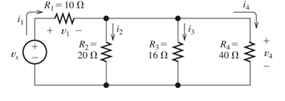
Figure T1.6
Expert Solution & Answer
Want to see the full answer?
Check out a sample textbook solution
Students have asked these similar questions
E
Figure 1.
R₁
L₁
M
1.Calculate coefficient of coupling k.
R₂
L₂
1₂
R₁
E = 230V 20°, R₁ = 100, R₂ = 0.50, R₂ = 2002, L₁= 10 H, L₂ = 26 mH, M = 0.5 H, f= 50Hz
Can you please give 5 examples of Kirchhoff's Voltage Law(KVL) with figure and complete solution each?(I need it for review)
Given n2 = 510, what is n₁?
5415° V
3060
85
1530
O 170
+21
000
ell
n₁: N₂
+
30415° V
Chapter 1 Solutions
Electrical Engineering: Principles & Applications (7th Edition)
Ch. 1 - Broadly speaking, what are the two main objectives...Ch. 1 - Prob. 1.2PCh. 1 - List eight subdivisions of electrical engineering.Ch. 1 - Prob. 1.4PCh. 1 - Prob. 1.5PCh. 1 - In the fluid-flow analogy for electrical circuits,...Ch. 1 - The charge of an electron is 1.601019C . A current...Ch. 1 - The ends of a length of wire are labeled a and b....Ch. 1 - The circuit element shown in Figure P1.9 has v=12V...Ch. 1 - Prob. 1.10P
Ch. 1 - The net charge through a cross section of a...Ch. 1 - The current through a particular circuit element...Ch. 1 - The current through a given circuit element is...Ch. 1 - The net charge through a cross section of a...Ch. 1 - A copper wire has a diameter of 2.05 mm and...Ch. 1 - A certain lead acid storage battery has a mass of...Ch. 1 - A circuit element having terminals a and b has...Ch. 1 - An electron moves through a voltage of 9 V from...Ch. 1 - A typical “deep-cycle” battery (used for electric...Ch. 1 - Define the term passive reference configuration....Ch. 1 - Compute the power for each element shown in Figure...Ch. 1 - The terminals of an electrical device are labeled...Ch. 1 - The terminals of a certain battery are labeled a...Ch. 1 - The element shown in Figure P1.24 I has v(t)=10V...Ch. 1 - The current and voltage of an electrical device...Ch. 1 - Suppose that the cost of electrical energy is...Ch. 1 - Figure P1.27 shows an ammeter (AM) and voltmeter...Ch. 1 - Repeat Problem P1.27 with the meters connected as...Ch. 1 - A certain type of D-cell battery that costs $0.50...Ch. 1 - The electronics aboard a certain sailboat consume...Ch. 1 - What s a node in an electrical circuit? Identify...Ch. 1 - State Kirchhoff’s current law.Ch. 1 - Two electrical elements are connected in series....Ch. 1 - Suppose that in the fluid-flow analogy for an...Ch. 1 - Identify elements that are in series in the...Ch. 1 - Consider the circuit shown in Figure P1.36. Which...Ch. 1 - Use KCL to find the values of ia, ic , and id for...Ch. 1 - Find the values of the other currents in Figure...Ch. 1 - Prob. 1.39PCh. 1 - State Kirchhoff’s voltage law.Ch. 1 - Consider the circuit shown in Figure P1.36. Which...Ch. 1 - Use KVL to solve for the voltages va , vb, and vc...Ch. 1 - Solve for the other voltages shown in Figure P1.43...Ch. 1 - Use KVL and KCL to solve for the labeled currents...Ch. 1 - Identify elements that are in parallel in Figure...Ch. 1 - Points a, b, c, and d appear in a certain circuit....Ch. 1 - In your own words, define an ideal conductor; an...Ch. 1 - Name four types of dependent sources and give the...Ch. 1 - State Ohm’s law, including references.Ch. 1 - Draw a circuit that contains a 5 resistance, a...Ch. 1 - Repeat Problem P1.50, placing all three elements...Ch. 1 - The resistance of a certain copper wire is 0.5. ....Ch. 1 - Draw a circuit that contains a 5 resistor, a 10-V...Ch. 1 - Draw a circuit that contains a 5 resistor, a 10-V...Ch. 1 - A power of 100 W is delivered to a certain...Ch. 1 - The voltage across a 10 resistor is given by...Ch. 1 - The voltage across a 10 resistor is given by...Ch. 1 - A certain wire has a resistance of 0.5 . Find the...Ch. 1 - Plot i versus v to scale for each of the parts of...Ch. 1 - Which of the following are self-contradictory...Ch. 1 - Consider the circuit shown in Figure P1.61. Find...Ch. 1 - Consider the circuit shown in Figure P1.62. Find...Ch. 1 - Consider the circuit shown in Figure P1.63. Find...Ch. 1 - Consider the circuit shown in Figure P1.64. Use...Ch. 1 - Determine the value of Ix in the circuit shown in...Ch. 1 - Consider the circuit shown in Figure P1.66. Figure...Ch. 1 - Prob. 1.67PCh. 1 - Consider the circuit shown in Figure P1.68. Figure...Ch. 1 - Solve for the currents shown in Figure P1.69....Ch. 1 - The circuit shown in Figure P1.70 contains a...Ch. 1 - Determine the value of vx and iy in the circuit...Ch. 1 - A 10-V independent voltage source is in series...Ch. 1 - A 10-V independent voltage source is in parallel...Ch. 1 - Consider the circuit shown in Figure P1.74. Figure...Ch. 1 - The circuit shown in Figure P1.75 contains a...Ch. 1 - For the circuit shown in Figure P1.76, solve for...Ch. 1 - For the circuit shown in Figure P1.77, solve for...Ch. 1 - Match each entry in Table T1.1(a) with the best...Ch. 1 - Prob. 1.2PTCh. 1 - The circuit of Figure T1.3 has I1=3A , I2=1A ,...Ch. 1 - The circuit shown in Figure T1.4 has Vs=12V ,...Ch. 1 - We are given Vs=15V , R=10 , and =0.3S for the...Ch. 1 - We are given i4=2A for the circuit of Figure T1.6....
Additional Engineering Textbook Solutions
Find more solutions based on key concepts
How many coulombs do 93.8 1016 electrons represent?
Principles Of Electric Circuits
Three point charges of equal magnitude q, that will yield a zero net electric field at the origin.
Engineering Electromagnetics
Analog Voltmeter Design Figure P2-98(a) shows a voltmeter circuit consisting of a D'Arsonval meter, two series ...
ANALYSIS+DESIGN OF LINEAR CIRCUITS(LL)
Electric power systems provide energy in a variety of commercial and industrial settings. Make a list of system...
Principles and Applications of Electrical Engineering
Write the nodal equations for the network of Fig. 8.137 using the general approach. Find the nodal voltages usi...
Introductory Circuit Analysis (13th Edition)
When travelers from the USA and Canada visit Europe, they encounter a different power distribution system. Wall...
Electric machinery fundamentals
Knowledge Booster


Learn more about
Need a deep-dive on the concept behind this application? Look no further. Learn more about this topic, electrical-engineering and related others by exploring similar questions and additional content below.Similar questions
- Find the potential difference between point a and point b for the situation shown below. Here ₁ = 12.0 V, E₂ = 8.77 V and R₁ = 4.13, R₂ = 5.44 , and R3 = 2.28 0. Va - Vb = R₂ V R3 R₁ Warrow_forwarda. Thévenin's and Norton's theorem are two examples of circuit theorem. With the help of equivalent circuits, distinguish the difference between them.arrow_forwardFind the potential difference between point a and point b for the situation shown below. Here ₁ = 12.0 V, E₂ = 7.77 V and R₁ = 4.33 №, R₂ = 6.44 , and R3 = 2.28 2. Va - Vb = R₂ E2 b R3 www R₁ &₁arrow_forward
- 2. For the circuit below, find i, iz, and is in the figure below. Assume I₁ = 4A, 12=0A, 13=4A, and 4-8 A. Show your work. A I₁ B C i2 13 Iarrow_forwardThe currents i and it in the circuit in the figure are 8.0 A and - 4.0 A, respectively. Vis 200 V. (Figure 1) Figure Part A Submit Part B Find ig Express your answer with the appropriate units. Value Va Request Answer 392 P⁹ P10 P30. P16 . Pii n. ps . P4. P15 = 502 m Units Find the power dissipated in each resistor. Enter your answers separated by commas. 15 02 m for Part A for Part Indo for Part redo for Part A reset for Part A keyboard shortcuts for Part A help for Part A 1102 ww TZ vec X for Part B for Part B for Part B for Part B 30 Ω ww 16 02 w 100 40 1 of 1 Vndo for Parts redo for Part B reset for Part B keyboard shortcuts for Part B help for Part B Warrow_forward8. Take that vs = 36 V Find the value of i1 in the figure. Find the value of i2 in the figure. .arrow_forward
- We are given i 4 = 2 A for the circuit of Figure T1.6. Use Ohm’s law, KCL, and KVL to find the values of i 1, i 2, i 3 and vs.arrow_forwardV = 36 V Refer to the figure at the right. iz What is the potential of point a with respect to point b when switch S is open? 3 0 What is the current through switch S S When it is closed? What is the equivalent resistance of this combination of resistors when S is closed?arrow_forwardThe circuit below(left) displays a schematic diagram of a battery. The voltage measured by U1 is called the terminal voltage given R1 = 1 ohm. In the circuit below(right), the terminal voltage of each of the battery-resistor combination is VT = 1.5 volts. Find the current passing through R1, R3, R5arrow_forward
- Three resistors of 10, 12 and X ohms, respectively are connected in parallel across a constant current source of 8A. Determine "X" if this resistor draws 2.13333333... A.arrow_forwardhow did you get I2= 45.45 angle -45.57 A? and where is the answer for current I1? Could you explain all of the steps of this solution and how you got each answer? I would really appreciate it.arrow_forwardQ2- Find the short circuit admittance parameters Y1 and Y1 for the circuit shown In the figure. 3h Va I2 V1 V2 1/2 /3arrow_forward
arrow_back_ios
SEE MORE QUESTIONS
arrow_forward_ios
Recommended textbooks for you
 Delmar's Standard Textbook Of ElectricityElectrical EngineeringISBN:9781337900348Author:Stephen L. HermanPublisher:Cengage Learning
Delmar's Standard Textbook Of Electricity
Electrical Engineering
ISBN:9781337900348
Author:Stephen L. Herman
Publisher:Cengage Learning
Kirchhoff's Rules of Electrical Circuits; Author: Flipping Physics;https://www.youtube.com/watch?v=d0O-KUKP4nM;License: Standard YouTube License, CC-BY