
Mechanics of Materials
9th Edition
ISBN: 9780133254426
Author: Russell C. Hibbeler
Publisher: Prentice Hall
expand_more
expand_more
format_list_bulleted
Videos
Textbook Question
Chapter 11.2, Problem 11.1FP
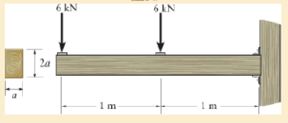
Determine the minimum dimension a to the nearest mm of the beam's cross section to safely support the load. The wood has an allowable normal stress of σallow = 10 MPa and an allowable shear stress of τallow = 1 MPa.
Expert Solution & Answer

Learn your wayIncludes step-by-step video

schedule06:11
Students have asked these similar questions
Determine the minimum dimension a to the nearest mm of the beam’s cross section to safely support the load. The wood has an allowable normal stress of sallow = 12 MPa and an allowable shear stress of tallow = 1.5 MPa.
Determine the shear stress (in Mpa) in the 28.54-mm-diameter pin at B that support the beam if P = 35.79 kN, a = 2.76 m, and b = 5.95 m.
If a = 3 in. and the wood has an allowable normal stress of sallow = 1.5 ksi, and an allowable shear stress of tallow = 150 psi, determine the maximum allowable value of P that can act on the beam.
Chapter 11 Solutions
Mechanics of Materials
Ch. 11.2 - Determine the minimum dimension a to the nearest...Ch. 11.2 - of the rod to safely support the load. The rod is...Ch. 11.2 - The wood has an allowable normal stress of allow =...Ch. 11.2 - of the beam's cross section to safely support the...Ch. 11.2 - Determine the minimum dimension b to the nearest...Ch. 11.2 - The beam is made of steel having an allowable...Ch. 11.2 - Determine its dimensions if it is to be...Ch. 11.2 - Determine the minimum width of the beam to the...Ch. 11.2 - if P=10 kip.Ch. 11.2 - If the allowable bending stress is allow = 22 ksi...
Ch. 11.2 - The allowable bending stress is allow = 24 ksi and...Ch. 11.2 - The allowable bending stress is allow = 22 ksi and...Ch. 11.2 - 11–7. Draw the shear and moment diagrams for the...Ch. 11.2 - *11–8. The simply supported beam is made of timber...Ch. 11.2 - The beam has an allowable normal stress of allow =...Ch. 11.2 - The beam has an allowable normal stress of allow...Ch. 11.2 - 11–11. The timber beam is to be loaded as shown....Ch. 11.2 - If each beam is to be designed to carry 90 lb/ft...Ch. 11.2 - 11–13. Select the lightest steel wide-flange beam...Ch. 11.2 - 11–14. Select the lightest-weight steel...Ch. 11.2 - Prob. 11.15PCh. 11.2 - The beam has an allowable normal stress of allow....Ch. 11.2 - Determine the maximum cable force P that can...Ch. 11.2 - to safely support the load. The wood has an...Ch. 11.2 - and the wood has an allowable normal stress of...Ch. 11.2 - Prob. 11.20PCh. 11.2 - Prob. 11.21PCh. 11.2 - Prob. 11.22PCh. 11.2 - 11–23. The beam is constructed from three boards...Ch. 11.2 - Prob. 11.24PCh. 11.2 - Prob. 11.25PCh. 11.2 - Select the lightest-weight wide-flange beam from...Ch. 11.2 - Prob. 11.27PCh. 11.2 - * 11–28. The joist AB used in housing construction...Ch. 11.2 - If the maximum bending stress is not to exceed...Ch. 11.2 - 11–30. The simply supported beam supports a load...Ch. 11.4 - Determine the variation in the width was a...Ch. 11.4 - Prob. 11.32PCh. 11.4 - Prob. 11.33PCh. 11.4 - The beam is made from a plate that has a constant...Ch. 11.4 - Determine the variation in the depth d of a...Ch. 11.4 - Determine the variation of the radius r of the...Ch. 11.4 - Prob. 11.37PCh. 11.4 - Determine the variation in the width b as a...Ch. 11.4 - The tubular shaft has an inner diameter of 15 mm....Ch. 11.4 - Prob. 11.40PCh. 11.4 - Prob. 11.41PCh. 11.4 - Prob. 11.42PCh. 11.4 - Prob. 11.43PCh. 11.4 - Prob. 11.44PCh. 11.4 - Prob. 11.45PCh. 11.4 - Prob. 11.46PCh. 11 - The cantilevered beam has a circular cross...Ch. 11 - Select the lightest-weight wide-flange overhanging...Ch. 11 - Prob. 11.49RPCh. 11 - Determine the shaft's diameter to the nearest...Ch. 11 - Select the lightest-weight wide-flange beam from...Ch. 11 - The simply supported joist is used in the...Ch. 11 - The simply supported joist is used in the...Ch. 11 - by 4-in. pieces of wood braced as shown. If the...
Additional Engineering Textbook Solutions
Find more solutions based on key concepts
the internal loading at point B.
Engineering Mechanics: Statics & Dynamics (14th Edition)
ICA 7-1
Express the following values using scientific notation, engineering notation, and using an appropriate ...
Thinking Like an Engineer: An Active Learning Approach (4th Edition)
Establish the location of the instantaneous center of zero velocity for finding the velocity of point B.
Engineering Mechanics: Dynamics (14th Edition)
The pipe assembly is subjected to the 80-N force. Determine the moment of this force about point A.
Engineering Mechanics: Statics
What parts are included in the vehicle chassis?
Automotive Technology: Principles, Diagnosis, and Service (5th Edition)
Determine the resultant internal loadings acting on the cross sections at points F and G of the frame. Probs. 7...
Statics and Mechanics of Materials (5th Edition)
Knowledge Booster


Learn more about
Need a deep-dive on the concept behind this application? Look no further. Learn more about this topic, mechanical-engineering and related others by exploring similar questions and additional content below.Similar questions
- Determine the shear stress (in Mpa) in the 23.5-mm-diameter pin at A that support the beam if P = 28.36 kN, a = 2.25 m, and b = 6.56 m.arrow_forwardThe double-web girder is constructed from two plywood sheets that are secured to wood members at its top and bottom. The allowable bending stress for the wood is σallow = 8 ksi and the allowable shear stress is τallow = 3 ksi. The fasteners are spaced s = 6 in. and each fastener can support 400 lb in single shear. Determine the maximum load P that can be applied to the beam.arrow_forwardbeam is supported by a roller and a hinge at its extremities. The 2 kN/m is loaded entirely on its 4 m length while 5 kN concentrated load is positioned 2 m from the left end of this beam. If the beam is 80 mm wide, determine the minimum height of the beam if the flexural stress is not to exceed 10 MPa.arrow_forward
- Determine the maximum shear force V that the strut can support if the allowable shear stress for the material is tallow = 40 MPa.arrow_forwardThe wood has an allowable normal stress of σallow = 15 MPa and an allowable shear stress ofτallowt = 1.33 MPa . Part A Determine the minimum dimension hh of the beam's cross section to safely support the load.arrow_forwardThe simply supported beam is built up from three boards by nailing them together as A, В shown. Determine the L1 L2 maximum allowable bf spacing s of the nails to support that load, if each nail can resist a tf tw shear force of V kN. hw tf P=17KN V=2kN L1=3.1m L2=2.5m bf=120mm tf=20mm hw=270mm tw=15mmarrow_forward
- The tension member is fastened together using two bolts, one on each side of the member as shown. Each bolt has a diameter of 0.3 in. Determine the maximum load P that can be applied to the member if the allowable shearstress for the bolts is tallow = 12 ksi and the allowable average normal stress is sallow = 20 ksi.arrow_forwardIf the beam is made of material having an allowable tensile and compressive stress of (sallow)t = 125 MPa and (sallow)c = 150 MPa, respectively, determine the maximum moment M that can be applied to the beam.arrow_forwardThe compound wooden beam is connected together by a bolt at B. Assuming that the connections at A, B, C, and D exert only vertical forces on the beam, determine the required diameter of the bolt at B and the required outer diameter of its washers if the allowable tensile stress for the bolt is 1st2allow = 150 MPa and the allowable bearing stress for the wood is 1sb2allow = 28 MPa. Assume that the hole in the washers has the same diameter as the bolt.arrow_forward
- 20 mm 20 mm 4. The simply supported beam on the right is built up from three boards by nailing them together as shown. If P = 12 kN, determine the maximum allowable spacing s of the nails to support the load, if each nail can resist a shear force of 1.5 kN. 1 m m B 100 mm 25 mm- 25 mm 200 mm 25 mmarrow_forwardDetermine the internal normal force at section A if the rod is subjected to the external uniformly distributed loading along its length of 8 kN>m.arrow_forwardThe pin is used to connect the three links together. Due to wear, the load is distributed over the top and bottom of the pin as shown on the free-body diagram. If the diameter of the pin is 0.40 in., determine the maximum bending stress on the cross-sectional area at the center section a–a. For the solution it is first necessary to determine the load intensities w1 and w2.arrow_forward
arrow_back_ios
SEE MORE QUESTIONS
arrow_forward_ios
Recommended textbooks for you
 Elements Of ElectromagneticsMechanical EngineeringISBN:9780190698614Author:Sadiku, Matthew N. O.Publisher:Oxford University Press
 Mechanics of Materials (10th Edition)Mechanical EngineeringISBN:9780134319650Author:Russell C. HibbelerPublisher:PEARSON
 Thermodynamics: An Engineering ApproachMechanical EngineeringISBN:9781259822674Author:Yunus A. Cengel Dr., Michael A. BolesPublisher:McGraw-Hill Education
 Control Systems EngineeringMechanical EngineeringISBN:9781118170519Author:Norman S. NisePublisher:WILEY
 Mechanics of Materials (MindTap Course List)Mechanical EngineeringISBN:9781337093347Author:Barry J. Goodno, James M. GerePublisher:Cengage Learning
 Engineering Mechanics: StaticsMechanical EngineeringISBN:9781118807330Author:James L. Meriam, L. G. Kraige, J. N. BoltonPublisher:WILEY
Elements Of Electromagnetics
Mechanical Engineering
ISBN:9780190698614
Author:Sadiku, Matthew N. O.
Publisher:Oxford University Press
Mechanics of Materials (10th Edition)
Mechanical Engineering
ISBN:9780134319650
Author:Russell C. Hibbeler
Publisher:PEARSON
Thermodynamics: An Engineering Approach
Mechanical Engineering
ISBN:9781259822674
Author:Yunus A. Cengel Dr., Michael A. Boles
Publisher:McGraw-Hill Education
Control Systems Engineering
Mechanical Engineering
ISBN:9781118170519
Author:Norman S. Nise
Publisher:WILEY
Mechanics of Materials (MindTap Course List)
Mechanical Engineering
ISBN:9781337093347
Author:Barry J. Goodno, James M. Gere
Publisher:Cengage Learning
Engineering Mechanics: Statics
Mechanical Engineering
ISBN:9781118807330
Author:James L. Meriam, L. G. Kraige, J. N. Bolton
Publisher:WILEY
Mechanics of Materials Lecture: Beam Design; Author: UWMC Engineering;https://www.youtube.com/watch?v=-wVs5pvQPm4;License: Standard Youtube License