
Videos
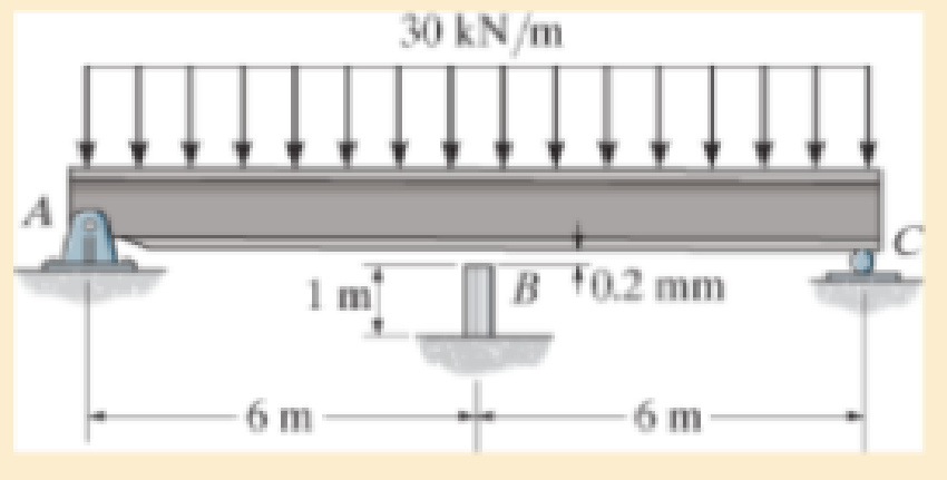
Before the uniform distributed load is applied to the beam, there is a small gap of 0.2 mm between the beam and the post at B. Determine the support reactions at A, B, and C. The post at B has a diameter of 40 mm, and the moment of inertia of the beam is I = 875 (106) mm4. The post and the beam are made of material having a modulus of elasticity of E = 200 GPa.
Want to see the full answer?
Check out a sample textbook solution
Chapter 12 Solutions
Mechanics of Materials
Additional Engineering Textbook Solutions
Automotive Technology: Principles, Diagnosis, and Service (5th Edition)
Automotive Technology: Principles, Diagnosis, And Service (6th Edition) (halderman Automotive Series)
Applied Fluid Mechanics (7th Edition)
Statics and Mechanics of Materials (5th Edition)
Thinking Like an Engineer: An Active Learning Approach (4th Edition)
Applied Statics and Strength of Materials (6th Edition)


- The bent bar is supported by smooth journal bearings at A, B and C and is subjected to couple moment of 200 N.m. Determine the support reaction at each of the smooth journal bearings. 200 N.m /0.4 m/ B 0.7 m 0.6 m Figure 2arrow_forwardThe horizontal beam is assumed to be rigid and supports the distributed load shown. Determine the vertical reactions at the supports. Each support consists of a wooden post having a diameter of 120 mm and an unloaded (original) length of 1.40 m. Take E = 12 GPa. The horizontal beam is assumed to be rigid and supports the distributed load shown. Determine the angle of tilt of the beam after the load is applied. Each support consists of a wooden post having a diameter of 120 mm and an unloaded (original) length of 1.40 m. Take Ew = 12 GPa. 18 kN/m A 1.40 m 2 m +1m-arrow_forwardThe beam ABis attached to the wall in the zz plane by a fixed support at A. A force of F = (- 156i + 58.0j + 350k) N is applied to the end of the beam at B. The weight of the beam can be modeled with a uniform distributed load of intensity w = 65.0 N/m acting in the negative z direction along its entire length. Find the support reactions at Á. F B y а Values for dimensions on the figure are given in the following table. Note the figure may not be to scale. Variable Value 5.80 m 5.00 m 3.80 m A = i+ j- k) N MA = k) N-marrow_forward
- Determine the reactions at A and B for the beam subjected to the couples and distributed load. At x = 0, the distributed load is increasing at the rate of 9 lb/ft per foot. Assume a = 5 ft, b = 20 ft, w₁ = 150 lb/ft, w₂ = 420 lb/ft, M₁ = 2630 lb-ft, M₂ = 1640 lb-ft. M₁ W | w = ko+k₁x + k₂x² potiu ·a+ b B W₂ M₂ -Xarrow_forwardThe horizontal beam is assumed to be rigid while supporting the distributed load. Determine the angle of inclination of the beam after the load is applied. Each support consists of a wooden post with a diameter of 120 mm and an original length (unloaded) of 1.40 m- Consider E = 12 GPaarrow_forwardIf the beam shown is supported by the fixed wall at B and the rod AC. if the rod has a cross sectional area = 10 x10-4 m2 and is made of the same material of the beam if the area moment of inertia of the beam's cross section is 9.7 x 10-° m4 if the distributed load w = 8.5 kN, then, the tension in the rod AC is . ... N 1 m 1 m 2 m Oa. 27.57 Ob.926.32 Oc 6.38 Od. 63518.95arrow_forward
- Determine the reactions at the supports. The moment of inertia for each segment is shown in the figure. Assume the support at B is a roller. Take E=29(10^3)ksiarrow_forward-4 ft- 5 ft R 4 ft A B (6,0,4) ft Given that the force in cable AB has a magnitude of TAB = 8 lbs and the unit vector in the direction of TAB is UAB=0.4361 -0.873j -0.218k. What is the moment reaction at the fixed support C? C and A have the same y-component. -65.5i -45.8j +52.4k ft-lb -52.41 -36.6j +41.9k ft-lb +52.4i +36.6j -41.9k ft-lb +65.5i +45.8j-52.4k ft-lb +34.91 +24.4j -27.9k ft-lb -34.91 -24.4j +27.9k ft-lbarrow_forwardProvide the correct exponents and distances to make the singularity function given valid for the beam shown. VI = 8 kN, V2 = 8 kN, V3 = 200 mm, and V4 = 1100 mm. Determine the reaction forces at the supports. A v3 V37 (m) o The singularity functions are q = R1(x)ª – v1( – P)ª – v2(x – Q)ª + R2(x – R)ª - 2 - V = R1 – v1(x – D)B – v2(x – E)B + R2(x – F)® (1) M = R1x – v1(x – G)° – v2(x – H)° + R2(x – (2) From the given singularity functions, the exponents are A = B = C= The distances are P= mm Q = mm R= mm D= mm E= mm F= mm G= mm H= mm mm Reactions force R = kN and reaction force R2 = kNarrow_forward
 Elements Of ElectromagneticsMechanical EngineeringISBN:9780190698614Author:Sadiku, Matthew N. O.Publisher:Oxford University Press
 Mechanics of Materials (10th Edition)Mechanical EngineeringISBN:9780134319650Author:Russell C. HibbelerPublisher:PEARSON
 Thermodynamics: An Engineering ApproachMechanical EngineeringISBN:9781259822674Author:Yunus A. Cengel Dr., Michael A. BolesPublisher:McGraw-Hill Education
 Control Systems EngineeringMechanical EngineeringISBN:9781118170519Author:Norman S. NisePublisher:WILEY
 Mechanics of Materials (MindTap Course List)Mechanical EngineeringISBN:9781337093347Author:Barry J. Goodno, James M. GerePublisher:Cengage Learning
 Engineering Mechanics: StaticsMechanical EngineeringISBN:9781118807330Author:James L. Meriam, L. G. Kraige, J. N. BoltonPublisher:WILEY