
Videos
- (a) For the circuit in Fig. 14.97, draw the new circuit after it has been scaled by Km = 200 and Kf = 104.
- (b) Obtain the Thevenin equivalent impedance at terminals a-b of the scaled circuit at ω = 104 rad/s.
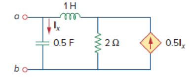
Figure 14.97
(a)
Draw the new circuit for the circuit in Figure 14.97 after it has been magnitude scaled by a factor of
Explanation of Solution
Given data:
Refer to Figure 14.97 in the textbook.
The value of the magnitude scaling factor
The value of the frequency scaling factor
Formula used:
Consider the equations used in magnitude and frequency scaling.
Write the expression to calculate the scaled resistor.
Here,
Write the expression to calculate the scaled inductor.
Here,
Write the expression to calculate the scaled capacitor.
Here,
Calculation:
The given circuit is redrawn as Figure 1.
Refer to Figure 1, the value of the resistor
Substitute
Substitute
Substitute
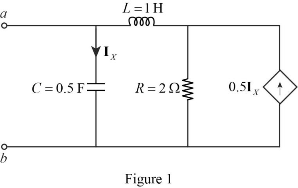
The redesigned circuit is drawn as Figure 2 which is obtained by using the magnitude and frequency scaling on the circuit in Figure 1.
Conclusion:
Thus, the new circuit for the circuit in Figure 14.97 is drawn by using the magnitude and frequency scaling.
(b)
Find the value of the Thevenin equivalent impedance at terminals a-b of the scaled circuit.
Answer to Problem 80P
The value of the Thevenin equivalent impedance
Explanation of Solution
Given data:
The value of the angular frequency
Formula used:
Write the expression to calculate the impedance of the passive elements resistor, inductor and capacitor in s-domain.
Here,
Calculation:
Use equation (4) to find
Use equation (5) to find
Use equation (6) to find
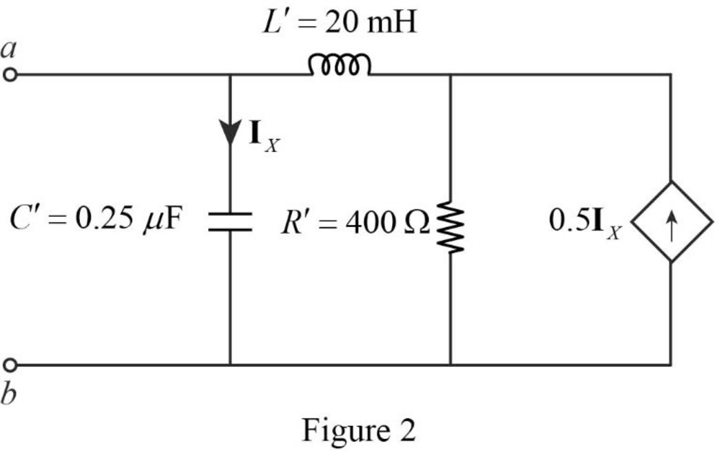
Insert a
Apply Kirchhoff’s current law on Figure 3 to find
Rearrange the above equation.
Apply Kirchhoff’s current law on Figure 3 to find
Refer to Figure 3, the current
Substitute
By comparing the equations (7) and (9), the following equation is obtained.
Rearrange the above equation to find
Substitute
Simplify the above equation.
Simplify the above equation to find
Refer to Figure 3, the Thevenin equivalent impedance across the a-b terminals are calculated as follows.
Substitute
Substitute
Substitute
Simplify the above equation to find
Conclusion:
Thus, the value of the Thevenin equivalent impedance
Want to see more full solutions like this?
Chapter 14 Solutions
Fundamentals of Electric Circuits


- The impedance of a series combination of a 10 resistor, a 10 capacitor, and a 10 inductor is a. 14.14 450 b. 14.14 -450 c. 10 90o d. 10 0oarrow_forwardA second order system with a natural frequency (wn) of 6 rad/sec and damping ratio of § = 0.5, the value of * rise time (tr) is equal to %3D 0.303 sec O 0.203 sec O 0.403 sec Carrow_forwardobtain Z-trans form for the Following XC+)= sin (t - 3T)arrow_forward
- The load is a series connection of a resistor RL with an inductor of 4.775 nH. Find the input impedance of this circuit at 2 GHz. RL=90 d = 2cm Zin = ? Zo = 500 Air-line Zo=500 l = 2cm Air-line ZLarrow_forward15. A series RLC circuit has elements R = 150 ohms, L = 18 mH and C= 2.22 microfarads. What is the equivalent impedance of the circuit if the frequency is 60 Hz?.arrow_forwardThe RC eircuit below is hooked up to a source that provides an emf of e(t) = Vocos(wt), where Vo = 40 V and w- 400 rad/s. R= 100 2, C = 8 x10- F. R (a) (b) (e) Find the circuit's impedance Z and maximum current lo- What is the maximum voltage read out over the capacitor? What is the phase difference o between the source emf and the current? (d) Draw a phase diagram for this circuit, labeling the phasors for all voltages and current and the phase angle ø. (e) How much average power does this circuit dissipate?arrow_forward
- It is known that the equivalent impedance of R=5 kiloOhm, L=4 H and Zab in the circuit given below is pure real (the imaginary part is zero). In this case, what is the operating frequency of the circuit in Hertz? a ict ir İR 5 - + D is)=10cos(500t+30°) mA Vo L R b O A) 500 Hz O B) 79.6 Hz 250 Hz O D) 50 Hz O E) 100 Hzarrow_forwardLet Zeq be the equivalent impedance of a series connection of an inductor with inductance L and a capacitor with capacitance C. At w=1/√√LC, the equivalent impedance is given by _ O a. Zeq = 00 O b. Zeq = 0 O c. Zeq = 0.5 O d. Zeq = 1arrow_forwardSimplify the expression: EE + CD + B+ A+E (CD + A)arrow_forward
- 11 For the circuit shown, the input impedance as seen by the source is..ohms. * 1 H F 80 11 12 140 cos 201 V 2 H 1 H 22 O 42.65<32.5 2+j36 O4+j76 1.78<98.56 O 16.68<76.2arrow_forward(h) In a standard parallel RC circuit, the supply voltage is v(t) = 6sin(ot), %3D f= 50 Hz, R =2Q and C= 5 mF. Find the total equivalent impedance in polar form.arrow_forwardA series R-L-C circuit has a resistance of 80 an inductance of 100mH and a capacitance of 5µF. If the current flowing is 2A, the impedance at resonance is: O a. 160 O b. 8m2 O c. 1600 O d. 80arrow_forward
 Introductory Circuit Analysis (13th Edition)Electrical EngineeringISBN:9780133923605Author:Robert L. BoylestadPublisher:PEARSON
 Delmar's Standard Textbook Of ElectricityElectrical EngineeringISBN:9781337900348Author:Stephen L. HermanPublisher:Cengage Learning
 Programmable Logic ControllersElectrical EngineeringISBN:9780073373843Author:Frank D. PetruzellaPublisher:McGraw-Hill Education
 Fundamentals of Electric CircuitsElectrical EngineeringISBN:9780078028229Author:Charles K Alexander, Matthew SadikuPublisher:McGraw-Hill Education
 Electric Circuits. (11th Edition)Electrical EngineeringISBN:9780134746968Author:James W. Nilsson, Susan RiedelPublisher:PEARSON
 Engineering ElectromagneticsElectrical EngineeringISBN:9780078028151Author:Hayt, William H. (william Hart), Jr, BUCK, John A.Publisher:Mcgraw-hill Education,