
Concept explainers
Videos
Find the total impedance of the parallel networks of Fig. 1663 in rectangular and polar form.
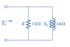
Fig. 1663
(a)
Total impedance of the given network.
Answer to Problem 1P
Rectangular form:
Polar form:
Explanation of Solution
Given:
The given network is:
Calculation:
We can see from the given circuit that the resistor
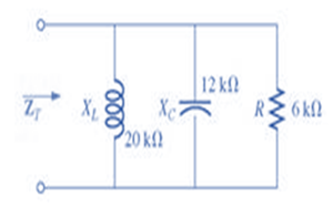
(b)
Total impedance of the given network.
Answer to Problem 1P
Rectangular form:
Polar form:
Explanation of Solution
Given:
The given network is:
Calculation:
We can see from the given circuit that the resistor
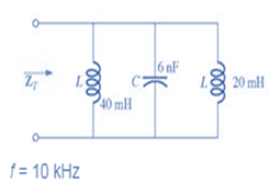
(c)
Total impedance of the given network.
Answer to Problem 1P
Rectangular form:
Polar form:
Explanation of Solution
Given:
The given network is:
Calculation:
We can see from the given circuit that two inductors and one capacitor are connected in parallel.
Therefore, we need to calculate their equivalent reactance first:
Inductive reactance of
Inductive reactance of
Capacitive reactance of
Therefore, the total resistance of the network will be:
Want to see more full solutions like this?
Chapter 16 Solutions
Introductory Circuit Analysis (13th Edition)
Additional Engineering Textbook Solutions
Engineering Electromagnetics
Principles and Applications of Electrical Engineering
Electric Circuits. (11th Edition)
Electric machinery fundamentals
Fundamentals of Applied Electromagnetics (7th Edition)
Programmable Logic Controllers


- 7. For the circuit in Fig. 126: a. Find the total impedance Zy in polar form. b. Draw the impedance diagram. R=80 X, =60 o FIG. 126 Problems 7 and 48.arrow_forwardSketch vo for each network and explain your solution.arrow_forwardFor the network shown in the Fig. below, write the nodal equations and solve for the nodal voltages. R6 2AI, REIN -M 20 205 202 www- Ru RS R3 1852 452 16 V- R₂arrow_forward
- 60 51 V2 V1 + V3 10 V 30 Ž40 330 Reference find V1, V2 using nodal analysisarrow_forwardFind Rab in the given network. Show complete solution.arrow_forwardOne of the laws governing the conservation of energy within electrical circuits stating that the sum of all currents leaving a node in an electrical network always equals zero. O Kirchhoff's Current Law O Kirchhoff's RLC Law O Kirov's RLC Law O Kirov's Current Lawarrow_forward
 Introductory Circuit Analysis (13th Edition)Electrical EngineeringISBN:9780133923605Author:Robert L. BoylestadPublisher:PEARSON
 Delmar's Standard Textbook Of ElectricityElectrical EngineeringISBN:9781337900348Author:Stephen L. HermanPublisher:Cengage Learning
 Programmable Logic ControllersElectrical EngineeringISBN:9780073373843Author:Frank D. PetruzellaPublisher:McGraw-Hill Education
 Fundamentals of Electric CircuitsElectrical EngineeringISBN:9780078028229Author:Charles K Alexander, Matthew SadikuPublisher:McGraw-Hill Education
 Electric Circuits. (11th Edition)Electrical EngineeringISBN:9780134746968Author:James W. Nilsson, Susan RiedelPublisher:PEARSON
 Engineering ElectromagneticsElectrical EngineeringISBN:9780078028151Author:Hayt, William H. (william Hart), Jr, BUCK, John A.Publisher:Mcgraw-hill Education,