
Concept explainers
Videos
Obtain the equivalent resistance Rab in each of the circuits of Fig. 2.117. In (b), all resistors have a value of 30 Ω.
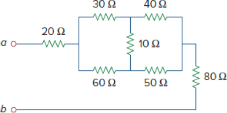
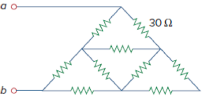
Figure 2.117
(a)
Calculate the equivalent resistor at terminals a-b in Figure 2.117(a).
Answer to Problem 53P
The equivalent resistor at terminals a-b in Figure 2.117(a) is
Explanation of Solution
Formula used:
Consider the delta to wye conversions.
Here,
Consider the expression for
Here,
Consider the expression for
Calculation:
Refer to Figure 2.117(a) in the textbook For Prob.2.53.
Step 1:
In Figure 2.117(a), convert the delta connection into wye connection.
Consider
Substitute
Substitute
Substitute
Modify Figure 2.117(a) as shown in Figure 1.
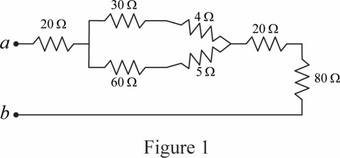
Step 2:
In Figure 1, as
Step 3:
In Figure 1, as
Step 4:
In Figure 1, as
Modify Figure 1 as shown in Figure 2.
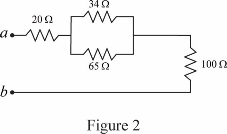
Step 5:
In Figure 2, as
Modify Figure 2 as shown in Figure 3.
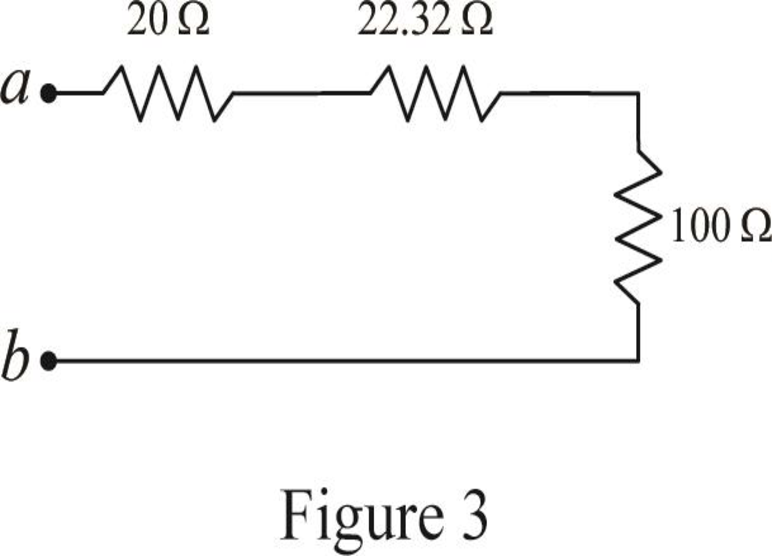
Step 6:
In Figure 3, as
Conclusion:
Thus, the equivalent resistor at terminals a-b in Figure 2.117(a) is
(b)
Calculate the equivalent resistor at terminals a-b in Figure 2.117(b).
Answer to Problem 53P
The equivalent resistor at terminals a-b in Figure 2.117(b) is
Explanation of Solution
Given data:
All resistance have
Formula used:
Consider the following delta to wye conversion, when all branches in a delta consist same value.
Calculation:
Refer to Figure 2.117(b) in the textbook For Prob.2.53.
Step 1:
In Figure 2.117(b), at left most corner of circuit, as two resistors are connected in series, therefore the equivalent resistance for series connected circuit is calculated as follows.
Step 2:
As
Modify Figure 2.117(b) as shown in Figure 4.
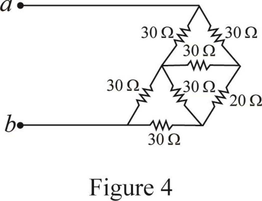
Step 3:
In Figure 4, as in upper part of the circuit all three
Substitute
Since all branch values are same in a delta connection that is
Modify Figure 4 as shown in Figure 5.
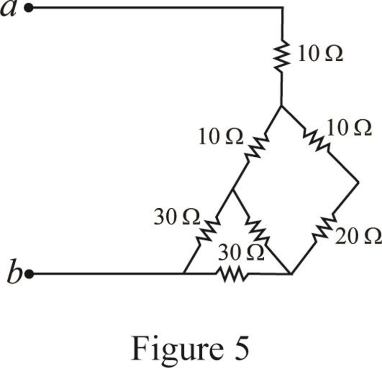
Step 4:
In Figure 5, as
Step 5:
In Figure 5, as in right most part of the circuit all three
Substitute
Since all branch values are same in a delta connection that is
Modify Figure 5 as shown in Figure 6.
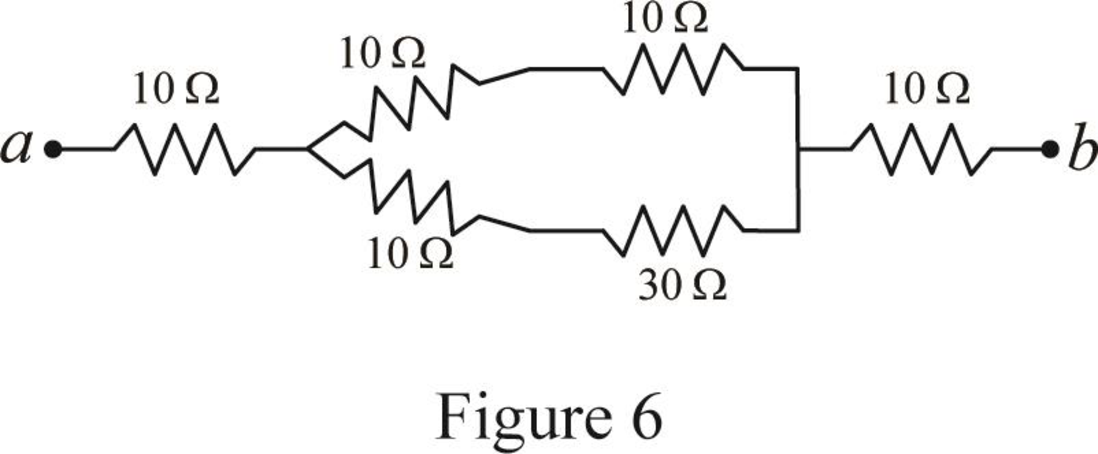
Step 6:
In Figure 6, as
Step 7:
In Figure 6, as
Step 8:
As
Modify Figure 6 as shown in Figure 7.
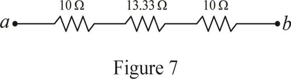
Step 4:
In Figure 7, as
Conclusion:
Thus, the equivalent resistor at terminals a-b in Figure 2.117(b) is
Want to see more full solutions like this?
Chapter 2 Solutions
Fundamentals of Electric Circuits
Additional Engineering Textbook Solutions
Electric Motors and Control Systems
Principles Of Electric Circuits
ANALYSIS+DESIGN OF LINEAR CIRCUITS(LL)
Programmable Logic Controllers
Electric Circuits. (11th Edition)
Principles and Applications of Electrical Engineering


- Exercise 1 1. Use the superposition principle to calculate the values in the circuit below. Enter these values in table B. Then build the circuit and measure the quantities. Record your measured values, along with percentage errors. 560 ohms R2 N 1.2k ohms 2.2k ohms R3 43 7V 2arrow_forwardQ₂ Q₂ Find (UCH) in the circuit of Figure below 1H Tort (1)V + ✓ CH 42 2.2 Farrow_forwardQ2/ Choose A or B: A- Use source transformation to determine the current and power absorbed by the 82 resistor for circuit illustrated below: 8Ω 3Ω ЗА (4 10 Q 6Ω +) 15 Varrow_forward
- 2. Assign references (label the circuit with your references) and write the KCL, KVL, and Ohms law equations necessary to analyze the circuit of Figure 1. You do not need to solve the resulting system of equations. HIH V1 12V R1 500Ω R2 21.5ΚΩ www Figure 2. Resistive Circuit 11 4mA R3 www 1kQ R4 1kQarrow_forwardTransform the circuit such that the 3 k2 resistor is left unchanged and the final circuit contain only the resistor and voltage source. From simplified circuit determine i and the power dissipated in 3 k2 resistor. 3 k2 13 k2 12 V 5 mA 2 k2 7 Varrow_forwardCalculate : a) Total resistance, RT b) T otal current ,IT from the source c) Current through resistor R3arrow_forward
- Determine the equivalent resistance across the terminals. 33 1 50 N 40 A 1012 32 2 60 N 10 3200 40 N 30 N b.arrow_forward2. Referring to Figure Q2, compute the maximum power that can be delivered to resistor (R). 9 V R 18 V (1) 5 A 80 Figure Q2arrow_forwardGiven the circuit of Figure below, find the total resistance, RT, and the total current, I. 10 2 30 V 30 N Z,60 N RT 10 N 10 Ω 90 Ω Page 6 of 6arrow_forward
- Find v2, if ix= -1mA (express your answer in milli (103))arrow_forward1. For Circuit 1, use classical circuit analysis (superposition might be a good choice) to determine the voltages VBB¹, VCc', and VBc. Remove the current and voltage sources and compute the resistance RÂ' that would be measured with an ideal ohmmeter. You must show detailed hand calculations to receive credit for your answers. A ww 12ΚΩ 15V B C 3kQ ΣΥΚΩ ΣΑΚΩ 5.1kΩ m W B' 2kQ C' 6kQ Circuit 1 D <5kQ D' 2mAarrow_forward22 V Part # 2 - 84 2 Thevenin resistance: ww 45 Ω www www + 42 92 23 V -O a 49 Ω For the circuit shown above, find the voltage and resistance of the Thevenin model seen at terminals a/b. (Assume that the plus sign of the Thevenin voltage goes toward terminal a.) Thevinin voltage: obarrow_forward
 Introductory Circuit Analysis (13th Edition)Electrical EngineeringISBN:9780133923605Author:Robert L. BoylestadPublisher:PEARSON
 Delmar's Standard Textbook Of ElectricityElectrical EngineeringISBN:9781337900348Author:Stephen L. HermanPublisher:Cengage Learning
 Programmable Logic ControllersElectrical EngineeringISBN:9780073373843Author:Frank D. PetruzellaPublisher:McGraw-Hill Education
 Fundamentals of Electric CircuitsElectrical EngineeringISBN:9780078028229Author:Charles K Alexander, Matthew SadikuPublisher:McGraw-Hill Education
 Electric Circuits. (11th Edition)Electrical EngineeringISBN:9780134746968Author:James W. Nilsson, Susan RiedelPublisher:PEARSON
 Engineering ElectromagneticsElectrical EngineeringISBN:9780078028151Author:Hayt, William H. (william Hart), Jr, BUCK, John A.Publisher:Mcgraw-hill Education,