
Videos
Determine the following for the pulse waveforms of Fig. 25.51:
a. whether it is positive-or negative-going
b. base-line voltage
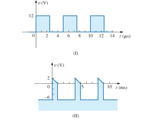
c. pulse width
d. amplitude
e. % tilt
(a)
Whether the waveform is positive going or negative going.
Answer to Problem 1P
The pulse waveform is positive going for case 1 and pulse waveform is positive going for case 2.
Explanation of Solution
Calculation:
Case 1:
Pulse waveform increases in positive direction from the base line therefore it is positive going pulse waveform.
Case 2:
Pulse waveform increases in positive direction from the base line therefore it is positive going pulse waveform.
Conclusion:
Thus, pulse waveform is positive going for case 1 and pulse waveform is positive going for case 2.
(b)
The value of base line voltage.
Answer to Problem 1P
The base line voltage is
Explanation of Solution
Concept used:
Base line voltage is the value of starting point voltage for pulse waveform.
Calculation:
Case 1:
In the waveform starting value of voltage is
Case 2:
In the waveform starting value of voltage is
Conclusion:
Thus, base line voltage is
(c)
The value of pulse width.
Answer to Problem 1P
The value of pulse width is
Explanation of Solution
Concept used:
Write the expression for pulse width.
Here,
Calculation:
Case 1:
Substitute
Therefore, value of pulse width is
Case 2:
Substitute
Therefore, value of pulse width is
Conclusion:
Thus ,value of pulse width is
(d)
The value of amplitude.
Answer to Problem 1P
The value of amplitude is
Explanation of Solution
Concept used:
Write the expression for peak to peak value.
Here,
Calculation:
Amplitude of pulse waveform is equal to peak to peak value of the waveform.
Case 1:
Substitute
The value of amplitude is
Case 2:
Substitute
The value of amplitude is
Conclusion:
Thus, value of amplitude is
(e)
The
Answer to Problem 1P
The
Explanation of Solution
Concept used:
Write the expression for
Here,
Calculation:
Case 1:
Substitute
Case 2:
Substitute
Conclusion:
Thus, the
Want to see more full solutions like this?
Chapter 25 Solutions
Introductory Circuit Analysis (13th Edition)
Additional Engineering Textbook Solutions
Fundamentals of Electric Circuits
Electrical Engineering: Principles & Applications (7th Edition)
Loose Leaf for Engineering Circuit Analysis Format: Loose-leaf
Electric machinery fundamentals
ANALYSIS+DESIGN OF LINEAR CIRCUITS(LL)
Microelectronics: Circuit Analysis and Design


- H.WI find the B function, frequency of oscillation and Re RE require for oscillation for the circuit shown below? {70 R Rf 3d Larrow_forwardThe maximum peak-to-peak value of an AM wave is 45 V. The peak-to-peak value of the modulating signal is 20 V. What is the percentage of modulation?arrow_forwardUsing two astable M.V timer .Desine the wave form shown in the figure below with Vec=9v, C= 1.6234.Mf . then 1-Determine the duty cycle and the frequency at the output of each M.V timer 2- Draw Vc and Vo at each cct. output o/P 0. 9.1 25 27 29.1 38.2 50 52 58.2 msarrow_forward
- 1.Is it possible to change time period of the waveform withoutchanging R & C? 2.Discuss the advantage and disadvantage of linear voltage regulator 3.Give four applications of voltage regulatorsarrow_forwardUsing two astable M.V timer .Desine the wave form shown in the figure below with Vcc=9v, C=1.6234.Mi . then 1-Determine the duty cycle and the frequency at the output of each M.V timer 2- Draw Vc and Vo at each cct. output o/P 9.1 25 27 29.1 38.2 50 52 58.2 msarrow_forwardThe average value of a full-wave rectified voltage with a peak value of 75 Vis a. 53 V b. 47.8 V C. 37.5 V O d. 23.9 Varrow_forward
- 1. A voltage regulator with a no-load output dc voltage of 12 V is connected to a load with a resistance of 10 ohms. If the load resistance decreases to 7.5 ohms, the load voltage will decrease to 10.9 V. What is the percent load regulation, and calculate the load current. 2. Determine the amount of anode voltage needed to turn on the PUT in the circuit as shown. Also determine oscillating frequency. R₁ • 470 ΚΩ +18 V AO 0.22 μF WI Va=+9 V -OK www R₂ 2202 R₂ ' 10 ΚΩ R₂ • 10 ΚΩarrow_forward(C) Q/ Determine and find dc level output ? the vo and sketch wave form, Vi 20 Vo 20 22/ Draw input is aud the the claipper circuit when the Sinwave with (p-p) Cn 20U) diode (si) connected in Seriesarrow_forwardDraw accurately the output waveform, show solution if needed.arrow_forward
 Introductory Circuit Analysis (13th Edition)Electrical EngineeringISBN:9780133923605Author:Robert L. BoylestadPublisher:PEARSON
 Delmar's Standard Textbook Of ElectricityElectrical EngineeringISBN:9781337900348Author:Stephen L. HermanPublisher:Cengage Learning
 Programmable Logic ControllersElectrical EngineeringISBN:9780073373843Author:Frank D. PetruzellaPublisher:McGraw-Hill Education
 Fundamentals of Electric CircuitsElectrical EngineeringISBN:9780078028229Author:Charles K Alexander, Matthew SadikuPublisher:McGraw-Hill Education
 Electric Circuits. (11th Edition)Electrical EngineeringISBN:9780134746968Author:James W. Nilsson, Susan RiedelPublisher:PEARSON
 Engineering ElectromagneticsElectrical EngineeringISBN:9780078028151Author:Hayt, William H. (william Hart), Jr, BUCK, John A.Publisher:Mcgraw-hill Education,