
Concept explainers
Videos
Repeat Prob. 3–8 using singularity functions exclusively (including reactions).
The reaction at the supports.
The shear force diagram.
The bending moment diagram.
Answer to Problem 12P
The reaction force
The reaction force
The reaction force
The shear force diagram is shown is below.

The bending moment diagram is shown below.

Explanation of Solution
The following figure shows the load applied to a beam.
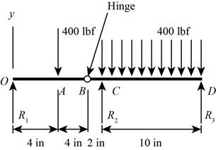
Figure-(1)
Refer to Table 3-1 “Singularity (Macaulay) functions”.
Write the expression for load intensity acting on the beam.
Here, the reaction force at point O is
Write the expression for the shear force.
Here, the net shear force is
Substitute the value from Equation (I) to Equation (II).
Write the expression for the moment.
Here, the net bending moment is
Substitute the value from Equation (III) to Equation (IV).
Conclusion:
Substitute
Thus, the reaction force
Substitute
Substitute
Thus, the reaction force
Substitute
Thus, the reaction force
Substitute the value of
The magnitude of shear force remains constant.
Substitute the value of
At
Substitute
At
Substitute
Similarly for the other values of
The Table-1 shows the variation of moment.
Table-1
Substitute the value of
The magnitude of shear force remains constant.
Substitute the value of
At
Substitute
At
Substitute
Similarly for the other values of
Table-2 shows the variation of moment.
Table-2
Substitute the value of
At
Substitute
At
Substitute
Similarly for the other values of
The Table-3 shows the variation of shear force.
Table-3
Substitute the value of
At
Substitute
At
Substitute
Similarly for the other values of
Differentiate Equation (X).
Equate the above expression to zero to obtain the location of maxima.
The Table-4 shows the variation of moment.
Table-4
The shear force diagram is shown in Figure-(2).
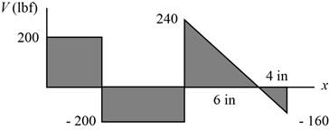
Figure-(2)
The bending moment diagram is shown in Figure-(3).
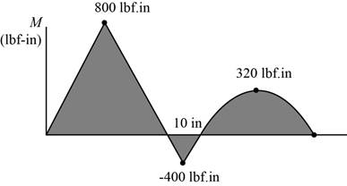
Figure-(3)
Want to see more full solutions like this?
Chapter 3 Solutions
Shigley's Mechanical Engineering Design (McGraw-Hill Series in Mechanical Engineering)


- Repeat Problem 11.3-9. Use two C 150 × 12.2 steel shapes and assume that E = 205 GPa and L = 6 m.arrow_forwardTwo circular aluminum pipes of equal length L = 24 in. arc loaded by torsional moments T (sec figure). Pipe I has outside and inside diameters d2= 3 in. and L2, = 2.5 in., respectively. Pipe 2 has a constant outer diameter of d2along its entire length L and an inner diameter of d1but has an increased inner diameter of d3= 2.65 in. over the middle third. Assume that E = 10,400 ksi, u = 0.33, and allowable shear stress ra= 6500 psi. Find the maximum acceptable torques that can be applied to Pipe 1; repeat for Pipe 2. If the maximum twist e of Pipe 2 cannot exceed 5/4 of that of Pipe 1, what is the maximum acceptable length of the middle segment? Assume both pipes have total length L and the same applied torque T. Find the new value of inner diameter d3of Pipe 2 if the maximum torque carried by Pipe 2 is to be 7/8 of that for Pipe L If the maximum normal strain in each pipe is known to bemax = 811 x 10-6, what is the applied torque on each pipe? Also, what is the maximum twist of each pipe? Use the original properties and dimensions.arrow_forwardSolve the preceding problem if the collar has mass M = 80 kg, the height h = 0.5 m, the length L = 3.0 m, the cross-sectional area A = 350mm2. and the modulus of elasticity E = 170 GPa.arrow_forward
- Solve the preceding problem for a W 200 × 41,7 shape with h = 166 mm, h = 205 mm. rw = 7.24 mm, tE= ILS mm,andV = 38 kN.arrow_forwardAn aluminum tube has inside diameter dx= 50 mm, shear modulus of elasticity G = 27 GPa, v = 0.33, and torque T = 4.0 kN · m. The allowable shear stress in the aluminum is 50 MPa, and the allowable normal strain is 900 X 10-6. Determine the required outside diameter d2 Re-compute the required outside diameter d2, if allowable normal stress is 62 MPa and allowable shear strain is 1.7 X 10-3.arrow_forwardA nonprismatic bar ABC with a solid circular cross section is loaded by distributed torques (sec figure). The intensity of the torques, that is, the torque per unit distance, is denoted t(x) and varies linearly from zero at A to a maximum value T0/L at B. Segment BC has linearly distributed torque of intensity r(x) = T0/3L of opposite sign to that applied along AB. Also, the polar moment of inertia of AB is twice that of BC and the shear modulus of elasticity of the material is G. Find the reaction torque RA. Find internal torsional moments T(x) in segments AB and BC. Find the rotation t0 Find the maximum shear stress tmaxand its location along the bar, Draw the torsional moment diagram (TMD:T(x),0 < x < L).arrow_forward
- Repeat Problem 3.3-1, but now use a circular tube with outer diameter d0= 2.5 in. and inner diameter di= 1.5 in.arrow_forwardSolve the preceding problem for sx= 11 MPa and ??y= -20 MPa (see figure).arrow_forwardA heavy flywheel rotating at n revolutions per minute is rigidly attached to the end of a shaft of diameter d (see figure). If the bearing at A suddenly freezes, what will be the maximum angle of twist <£of the shaft? What is the corresponding maximum shear stress in the shaft? (Let L = length of the shaft, G = shear modulus of elasticity, and / = mass moment of inertia of the flywheel about the axis of the shaft. Also, disregard friction in the bearings at Sand Cand disregard the mass of the shaft.) Hint: Equate the kinetic energy of the rotating flywheel to the strain energy of the shaft.arrow_forward
- Solve the preceding problem if the shaft has an outer diameter d2=150 mm and inner diameter d1= 100 mm. Also, the steel has a shear modulus of elasticity G = 75 GPa, and the applied torque is 16 kN ·m.arrow_forwardSolve the preceding problem for a steel pipe column (E = 210 GPa) with length L = 1.2 m, inner diameter d2= 36 mm, and outer diameter d2=40 mm.arrow_forwardTwo sections of steel drill pipe, joined by bolted flange plates at Ä are being tested to assess the adequacy of both the pipes. In the test, the pipe structure is fixed at A, a concentrated torque of 500 kN - m is applied at x = 0.5 m, and uniformly distributed torque intensity t1= 250 kN m/m is applied on pipe BC. Both pipes have the same inner diameter = 200 mm. Pipe AB has thickness tAB=15 mm, while pipe BC has thickness TBC= 12 mm. Find the maximum shear stress and maximum twist of the pipe and their locations along the pipe. Assume G = 75 GPa.arrow_forward
 Mechanics of Materials (MindTap Course List)Mechanical EngineeringISBN:9781337093347Author:Barry J. Goodno, James M. GerePublisher:Cengage Learning