
Concept explainers
Videos
Using appropriate measurements and data, explain how to determine the bending stress in the blade.
C6–1
Answer to Problem 6.1CP
The bending stress in the blade is
Explanation of Solution
Given information:
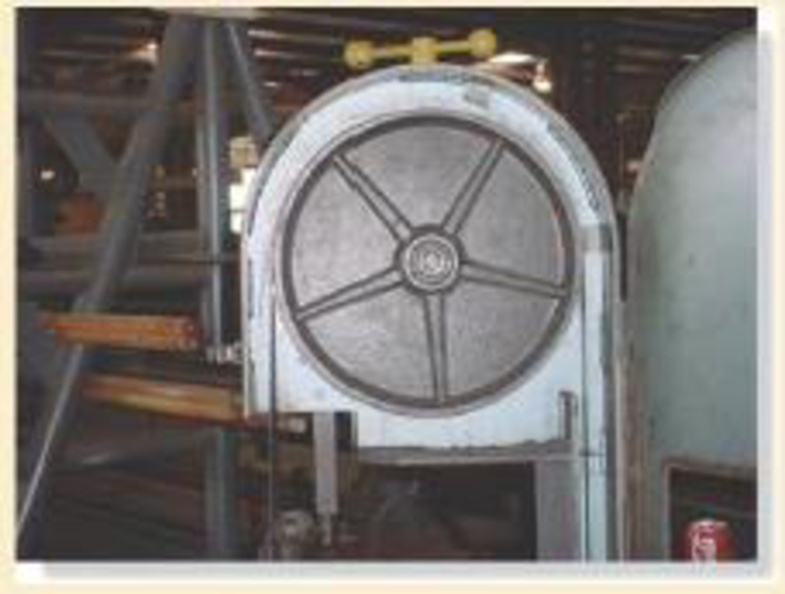
- The steel saw blade passes over the drive wheel of the band saw.
- Use appropriate measurements and data.
Explanation:
The contact area of the cable is upper half portion of the drive wheel. The, the upper half portion of the wheel will undergo stress.
Show the free-body diagram of the drive wheel as in Figure 1.
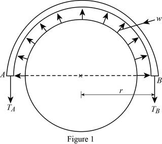
The force induced in the drive wheel will be uniformly distributed.
The circumferential distance of the circular section is
Convert the semi-circular section into beam section as in Figure 2.
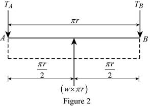
Determine the tension in the cable:
Moment about point A:
Determine the tension in the cable at point B by taking moment about point A.
Along the vertical direction:
Determine the tension in the cable at point A by resolving the vertical component of forces.
Show the calculation of values as follows:
Solve Equation (1).
Substitute
Maximum Bending moment:
The maximum bending moment will occur where the shear force changes sign
Consider a section at a distance x from left end of the beam.
Show the free body diagram of the section as in Figure 3.
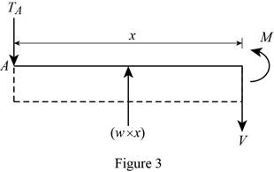
Along the vertical direction:
Determine the shear force at the section by resolving the vertical component of forces.
Moment about the section:
Determine the moment at the section by taking moment about the section.
Substitute 0 for V and
Thus, the maximum bending moment will occur at a distance
Substitute
Bending stress:
Calculate the bending stress in the blade using the flexure formula.
Here, c is the distance between the centroid and the extreme fibre and I is moment of inertia of the band saw.
Consider the band saw is in rectangular cross section.
The value of c is
The moment of inertia of the band saw is
Here, b is width of the section and d is depth of the section.
Substitute
Thus, the bending stress in the blade is
Want to see more full solutions like this?
Chapter 6 Solutions
Mechanics of Materials (10th Edition)


- These garden shears were manufactured using an inferior material. Using a loading of 50 lb applied normal to the blades, and appropriate dimensions for the shears, determine the absolute maximum bending stress in the material and show why the failure occurred at the critical location on the handle.arrow_forwardThese garden shears were manufactured using inferior material. Using a loading of 50 lb applied normal to the blades, and appropriate dimensions for the shears, determine the absolute maximum bending stress in thematerial and show why the failure occurred at the critical location on the handle.arrow_forwardThe stepped bar has a thickness of 30 mm 90 mm 60 mm 20 mm 7.5 mm 15 mm M M Part A Determine the maximum moment that can be applied to its ends if the allowable bending stress is oallow = 190 MPa Express your answer to three significant figures and include appropriate units. μΑ M = Value Unitsarrow_forward
- Problem 1 Please choose the correct answer and also write down your solution. (1) The section supports an upward internal shear force and a clockwise internal torque. Where does the absolute maximum shear stress occur? a. Point A b. Point B c. Point C d. Point D (2) The internal force and moment of the section have been determined as F = 100î + 300k (N) and M = 50î + 40j (N - m). Where does the absolute maximum normal stress occur? a. Point A b. Point B c. Point C d. Point Darrow_forwardProduce the Shear Force and Bending Moment Diagram.where Roll No=11arrow_forwardProduce the Shear Force and Bending Moment Diagram. where Roll No=11arrow_forward
- For the beam shown, find the reactions at the supports and plot the shear-force and bending-moment diagrams. V = 7 kN, V2 = 7 kN, V3 = 100 mm, and V4 = 1300 mm. (mm) 0 Provide values at all key points shown the given shear-force and bending-moment diagrams. X (mm) A C V2 B E D F 0.00 +V Reaction force R₁ (left) = In the shear-force and bending-moment diagrams given, 0.00 X (mm) kN and reaction force R₂ (right) = P KN. 0.00arrow_forwardThe 46-mm diameter shaft is supported by a smooth thrust bearing at A and a smooth journal bearing at B. The pulleys C and D are subjected to the vertical and horizontal loadings shown in the figure below. (Figure 1) Part A Determine the absolute maximum bending stress in the shaft. Express your answer to three significant figures and include the appropriate units. ? Omax = 10.7 MPa Submit Previous Answers Request Answer X Incorrect; Try Again; 29 attempts remaining Provide Feedback Figure 150 N 400 mm 150 N 300 N 300 N 400 mm 400 mmarrow_forwardDetermine the outer and inner diameter (in mm) of a hollow shaft that is required to carry a bending moment of 2000 N-m and a torque of 4300 N-m if the diameter of the hole is equal to 0.7 of the outer diameter of the shaft. The shaft rotates and loads are applied gradually. The maximum bending stress is equivalent to 80 N/mm2. Apply ASME Code for this problem.arrow_forward
- Determine the normal force, shear force and moment at point C and D. Express your answer in kilopounds to three significant figuresPlease give the final values of answer at last as wellarrow_forwardDetermine the maximum positive normal bending stress that occurs in member ABC of the engine crane given the following information: Engine weight = 1500 lb Member ABC height (vertical cross sectional dimension) = 7 in Member ABC width (horizontal cross sectional dimension) = 1 in Express your answer to the nearest whole psi value. In your work, draw the shear and moment diagram for member ABC. For the question above, determine the maximum shear stress in member ABC that occurs between points A and B. Express your answer using the nearest whole psi value.arrow_forwardQuestion 1: Draw the shear and bending moment diagram for the following structure P₁ = 100 lb A 77X01 -1 ft- B w = 10 lb/ft -2 ft- -4.5 ft- mi -1.5 ft- P₂ = 80 lb Darrow_forward
 Elements Of ElectromagneticsMechanical EngineeringISBN:9780190698614Author:Sadiku, Matthew N. O.Publisher:Oxford University Press
 Mechanics of Materials (10th Edition)Mechanical EngineeringISBN:9780134319650Author:Russell C. HibbelerPublisher:PEARSON
 Thermodynamics: An Engineering ApproachMechanical EngineeringISBN:9781259822674Author:Yunus A. Cengel Dr., Michael A. BolesPublisher:McGraw-Hill Education
 Control Systems EngineeringMechanical EngineeringISBN:9781118170519Author:Norman S. NisePublisher:WILEY
 Mechanics of Materials (MindTap Course List)Mechanical EngineeringISBN:9781337093347Author:Barry J. Goodno, James M. GerePublisher:Cengage Learning
 Engineering Mechanics: StaticsMechanical EngineeringISBN:9781118807330Author:James L. Meriam, L. G. Kraige, J. N. BoltonPublisher:WILEY