
Engineering Mechanics: Statics & Dynamics (14th Edition)
14th Edition
ISBN: 9780133915426
Author: Russell C. Hibbeler
Publisher: PEARSON
expand_more
expand_more
format_list_bulleted
Videos
Textbook Question
Chapter 6.6, Problem 74P
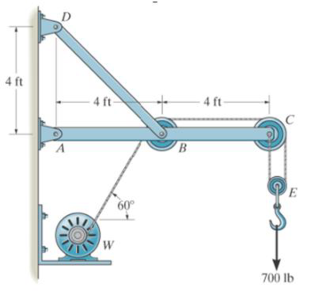
The wall crane supports a load of 700 lb. Determine the horizontal and vertical components of reaction at the pins A and D. Also, what is the force in the cable at the winch W?
Prob. 6-74/75
Expert Solution & Answer
Want to see the full answer?
Check out a sample textbook solution
Students have asked these similar questions
tension or compression. Approximate each joint as a pin.
6-23. The Fink truss supports the loads shown. Determine
the force in each member and state if the members are in
or
500 lb
1000 lb
2.5 ft
1000 lb
2.5 ft
ID
1000 lb
30°
2.5 ft
500 lb 2.5 ft
30°
A
H
Prob. 6-23
6-85.
The three power lines exert the forces shown on the truss
joints, which in turn are pin-connected to the poles AH and
EG. Determine the force in the guy cable AI and the pin
reaction at the support H.
20 ft
D
B
-40 ft--40 ft-
800 lb
800 lb
H
800 lb
-50 ft-30 ft--30
20 ft
-30 ft-30 ft-30 ft-30 ft
30 ft-30
20 ft
ft-50 ft-
125 ft
Determine the horizontal and vertical components
of reaction at the pin A and the tension developed in cable
BC used to support the steel frame.
•5
60 kN
m1m
1m
30 kN m
3 m
Prob. 5-21
Chapter 6 Solutions
Engineering Mechanics: Statics & Dynamics (14th Edition)
Ch. 6.3 - In each case, calculate the support reactions and...Ch. 6.3 - Identify the zero-force members in each truss....Ch. 6.3 - Determine the force in each member of the truss....Ch. 6.3 - Determine the force in each member of the truss....Ch. 6.3 - Determine the force in each member of the truss....Ch. 6.3 - Determine the greatest load P that can be applied...Ch. 6.3 - Identify the zero-force members in the truss....Ch. 6.3 - Determine the force in each member of the truss....Ch. 6.3 - Determine the force in each member of the truss...Ch. 6.3 - Determine the force in each member of the truss...
Ch. 6.3 - Determine the force in each member of the truss....Ch. 6.3 - Determine the force in each member of the truss...Ch. 6.3 - Prob. 5PCh. 6.3 - Determine the force in each member of the truss,...Ch. 6.3 - Determine the force in each member of the truss...Ch. 6.3 - Determine the force in each member of the truss...Ch. 6.3 - Prob. 9PCh. 6.3 - Determine the force in each member of the truss...Ch. 6.3 - Determine the force in each member of the Pratt...Ch. 6.3 - Determine the force in each member of the truss...Ch. 6.3 - Determine the force in each member of the truss in...Ch. 6.3 - Members AB and BC can each support a maximum...Ch. 6.3 - Members AB and BC can each support a maximum...Ch. 6.3 - Determine the force in each member of the truss....Ch. 6.3 - If the maximum force that any member can support...Ch. 6.3 - Determine the force in each member of the truss...Ch. 6.3 - Determine the force in each member of the truss...Ch. 6.3 - Prob. 20PCh. 6.3 - Determine the force in each member of the truss...Ch. 6.3 - Determine the force in each member of the double...Ch. 6.3 - Prob. 23PCh. 6.3 - The maximum allowable tensile force in the members...Ch. 6.3 - Determine the force in each member of the truss in...Ch. 6.3 - The maximum allowable tensile force in the members...Ch. 6.4 - Determine the force in members BC, CF, and FE....Ch. 6.4 - Determine the force in members LK, KC, and CD of...Ch. 6.4 - Determine the force in members KJ, KD, and CD of...Ch. 6.4 - Determine the force in members EF, CF, and BC of...Ch. 6.4 - Determine the force in members GF, GD, and CD of...Ch. 6.4 - Determine the force in members DC, HI, and JI of...Ch. 6.4 - Determine the force in members DC, HC, and HI of...Ch. 6.4 - Determine the force in members ED, EH, and GH of...Ch. 6.4 - Determine the force in members HG, HE and DE of...Ch. 6.4 - Determine the force in members CD, HI, and CH of...Ch. 6.4 - Prob. 31PCh. 6.4 - Prob. 32PCh. 6.4 - Prob. 33PCh. 6.4 - Prob. 34PCh. 6.4 - Determine the force in members EF, CF, and BC, and...Ch. 6.4 - Determine the force in members AF, BF, and BC, and...Ch. 6.4 - Prob. 39PCh. 6.4 - Determine the force in members CD, CF, and CG and...Ch. 6.4 - Determine the force developed in members FE, EB,...Ch. 6.4 - Determine the force in members BC, HC, and HG....Ch. 6.4 - Determine the force in members CD, CJ, GJ, and CG...Ch. 6.4 - Determine the force in members BE, EF, and CB, and...Ch. 6.4 - Prob. 45PCh. 6.4 - Determine the force in members BC, CH, GH, and CG...Ch. 6.4 - Determine the force in members CD, CJ, and KJ and...Ch. 6.4 - Prob. 48PCh. 6.4 - Determine the force in members HI, FI, and EF of...Ch. 6.6 - In each case, identify any two-force members, and...Ch. 6.6 - Determine the force P needed to hold the 60-lb...Ch. 6.6 - Determine the horizontal and vertical components...Ch. 6.6 - If a 100-N force is applied to the handles of the...Ch. 6.6 - Determine the horizontal and vertical components...Ch. 6.6 - Determine the normal force that the 100-lb plate A...Ch. 6.6 - Determine the force P needed to lift the load....Ch. 6.6 - Prob. 19FPCh. 6.6 - Prob. 20FPCh. 6.6 - Determine the components of reaction at A and C....Ch. 6.6 - Determine the components of reaction at C. Prob....Ch. 6.6 - Determine the components of reaction at E. Prob....Ch. 6.6 - Determine the components of reaction at D and the...Ch. 6.6 - Determine the force P required to hold the 100-lb...Ch. 6.6 - In each case, determine the force P required to...Ch. 6.6 - Determine the force P required to hold the 50-kg...Ch. 6.6 - Determine the force P required to hold the 150-kg...Ch. 6.6 - Determine the horizontal and vertical components...Ch. 6.6 - Determine the horizontal and vertical components...Ch. 6.6 - Determine the force that the smooth rotor C exerts...Ch. 6.6 - The bridge frame consists of three segments which...Ch. 6.6 - Determine the reactions at supports A and B. Prob....Ch. 6.6 - Determine the horizontal and vertical components...Ch. 6.6 - Determine the reactions at the supports A, C, and...Ch. 6.6 - Determine the resultant force at pins A, B, and C...Ch. 6.6 - Determine the reactions at the supports at A, E,...Ch. 6.6 - The wall crane supports a load of 700 lb....Ch. 6.6 - The wall crane supports a load of 700 lb....Ch. 6.6 - Determine the horizontal and vertical components...Ch. 6.6 - The two-member structure is connected at C by a...Ch. 6.6 - The compound beam is pin supported at B and...Ch. 6.6 - When a force of 2 lb is applied to the handles of...Ch. 6.6 - The toggle clamp is subjected to a force F at the...Ch. 6.6 - The hoist supports the 125-kg engine. Determine...Ch. 6.6 - A 5-lb force is applied to the handles of the vise...Ch. 6.6 - Determine the force in members FD and DB of the...Ch. 6.6 - Determine the force that the smooth 20-kg cylinder...Ch. 6.6 - Prob. 85PCh. 6.6 - The pumping unit is used to recover oil. When the...Ch. 6.6 - Determine the force that the jaws J of the metal...Ch. 6.6 - Prob. 88PCh. 6.6 - Determine the horizontal and vertical components...Ch. 6.6 - The pipe cutter is clamped around the pipe P. If...Ch. 6.6 - Determine the force created in tire hydraulic...Ch. 6.6 - Determine the horizontal and vertical components...Ch. 6.6 - The constant moment of 50 N m is applied to the...Ch. 6.6 - Five coins are stacked in the smooth plastic...Ch. 6.6 - The nail cutter consists of the handle and the two...Ch. 6.6 - A man having a weight of 175 lb attempts to hold...Ch. 6.6 - Prob. 97PCh. 6.6 - The two member frame is pin connected at E. The...Ch. 6.6 - If the 300 kg drum has a center of mass at point...Ch. 6.6 - Operation of exhaust and intake valves in an...Ch. 6.6 - If a clamping force of 300 N is required at A,...Ch. 6.6 - If a force of F = 350 N is applied to the handle...Ch. 6.6 - Determine the horizontal and vertical components...Ch. 6.6 - The hydraulic crane is used to lift the 1400-lb...Ch. 6.6 - Determine force P on the cable if the spring is...Ch. 6.6 - Prob. 106PCh. 6.6 - If a force of F = 50 lb is applied to the pads at...Ch. 6.6 - The skid-steer loader has a mass of 1.18 Mg, and...Ch. 6.6 - Determine the force P on the cable if the spring...Ch. 6.6 - The spring has an unstretched length of 0.3 m....Ch. 6.6 - The spring has an unstretched length of 0.3 m....Ch. 6.6 - The piston C moves vertically between the two...Ch. 6.6 - Prob. 113PCh. 6.6 - The platform scale consists of a combination of...Ch. 6.6 - The three pin-connected members shown in the top...Ch. 6.6 - Determine the force in each member of the truss...Ch. 6.6 - Determine the force in each member of the truss...Ch. 6.6 - Determine the force in member GJ and GC of the...Ch. 6.6 - Determine the force in members GF, FB, and BC of...Ch. 6.6 - Determine the horizontal and vertical components...Ch. 6.6 - Determine the horizontal and vertical components...Ch. 6.6 - Determine the resultant forces at pins B and C on...
Knowledge Booster


Learn more about
Need a deep-dive on the concept behind this application? Look no further. Learn more about this topic, mechanical-engineering and related others by exploring similar questions and additional content below.Similar questions
- *5-8. Draw the free-body diagram of member ABC which is supported by a smooth collar at A, roller at B, and short link CD. Explain the significance of each force acting on the diagram. (See Fig. 5-7b.) 2.5 kN 3 m 4kN m 4 m 6m Prob. 5-8arrow_forward6-51. Determine the force in each member of the space truss and state if the members are in tension or compression. The truss is supported by short links at A, B, and C. 4 ft. X 2 ft D Z 8 ft B Prob. 6-51 {500j} lb 3 ft 2 ft yarrow_forward6-40. The compound beam is fixed supported at C and supported by rockers at A and B. If there are hinges (pins) at D and E, determine the components of reaction at the supports. Neglect the thickness of the beam. 900 lb 400 lb A 0 2 ft 300 lb B FRESSPOR -6 ft4 ft 4 ft D 4 ft- 2 ft Prob. 6-40 E 650 lb 13/12 2 ft C -8 ft- 4arrow_forward
- 6-9. Determine the force in each member of the truss state if the members are in tension or compression. P₁ = 800 lb, P₂ = 600 lb. bers 10 ft - A P₂ 30⁰ B 60° 10 ft- P₁ с F D 60° Prob. 6-9 30° -10 ft-arrow_forward•5-21. Determine the horizontal and vertical components of reaction at the pin A and the tension developed in cable BC used to support the steel frame. 60 kN -1m-1 m- 1 m- B 30 kN · m 3 m 3. Aarrow_forwardF5-1. Determine the horizontal and vertical components of reaction at the supports. Neglect the thickness of the beam. 500 Ib 600 lb - ft B Esan to -5 ft- -5 t- -5 ft-arrow_forward
- 3-2. The members of a truss are pin connected at joint O. Determine the magnitude of F, and its angle for equilibrium. Set F - 6 KN. 5 kN 70 30 7 KN Probs. 3-1/2arrow_forward6-53 Determine the force exerted by the cable at B and the reaction at support A of the bar shown in Fig. D 20 60° B 800 lb 3 ft 3 ftarrow_forward6-98. The two-member frame is pin connected at E. The cable is attached to D, passes over the smooth peg at C, and supports the 500-N load. Determine the horizontal and vertical reactions at each pin. 0.5 m 0.5 m -1 m 1 m 0.5 m (E D 500 Narrow_forward
- P5-3. then draw the free-body diagrams of each member of the identify any two-force members, and frame. 400 N/m -3 m 1marrow_forward•5-21. Determine the horizontal and vertical components of reaction at the pin A and the tension developed in cable BC used to support the steel frame. 60 kN 1m-1m- 1 m- B 30 kN m 3 m 5 COarrow_forward•5-21. Determine the horizontal and vertical components of reaction at the pin A and the tension developed in cable BC used to support the steel frame. 60 kN -1 m1 m -1 m B 30 kN m 3 m 4 3 Iarrow_forward
arrow_back_ios
SEE MORE QUESTIONS
arrow_forward_ios
Recommended textbooks for you
 Elements Of ElectromagneticsMechanical EngineeringISBN:9780190698614Author:Sadiku, Matthew N. O.Publisher:Oxford University Press
 Mechanics of Materials (10th Edition)Mechanical EngineeringISBN:9780134319650Author:Russell C. HibbelerPublisher:PEARSON
 Thermodynamics: An Engineering ApproachMechanical EngineeringISBN:9781259822674Author:Yunus A. Cengel Dr., Michael A. BolesPublisher:McGraw-Hill Education
 Control Systems EngineeringMechanical EngineeringISBN:9781118170519Author:Norman S. NisePublisher:WILEY
 Mechanics of Materials (MindTap Course List)Mechanical EngineeringISBN:9781337093347Author:Barry J. Goodno, James M. GerePublisher:Cengage Learning
 Engineering Mechanics: StaticsMechanical EngineeringISBN:9781118807330Author:James L. Meriam, L. G. Kraige, J. N. BoltonPublisher:WILEY
Elements Of Electromagnetics
Mechanical Engineering
ISBN:9780190698614
Author:Sadiku, Matthew N. O.
Publisher:Oxford University Press
Mechanics of Materials (10th Edition)
Mechanical Engineering
ISBN:9780134319650
Author:Russell C. Hibbeler
Publisher:PEARSON
Thermodynamics: An Engineering Approach
Mechanical Engineering
ISBN:9781259822674
Author:Yunus A. Cengel Dr., Michael A. Boles
Publisher:McGraw-Hill Education
Control Systems Engineering
Mechanical Engineering
ISBN:9781118170519
Author:Norman S. Nise
Publisher:WILEY
Mechanics of Materials (MindTap Course List)
Mechanical Engineering
ISBN:9781337093347
Author:Barry J. Goodno, James M. Gere
Publisher:Cengage Learning
Engineering Mechanics: Statics
Mechanical Engineering
ISBN:9781118807330
Author:James L. Meriam, L. G. Kraige, J. N. Bolton
Publisher:WILEY
Physics 33 - Fluid Statics (1 of 10) Pressure in a Fluid; Author: Michel van Biezen;https://www.youtube.com/watch?v=mzjlAla3H1Q;License: Standard YouTube License, CC-BY