
Videos
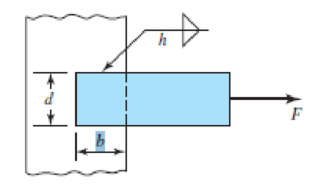
9–1 to 9–4 The figure shows a horizontal steel bar of thickness h loaded in steady tension and welded to a vertical support. Find the load F that will cause an allowable shear stress, τallow, in the throats of the welds.
| Problem Number | b | d | h | τallow |
| 9–1 | 50 mm | 50 mm | 5 mm | 140 Mpa |
| 9–2 | 2 in | 2 in |
|
25 kspi |
| 9–3 | 50 mm | 30 mm | 5 mm | 140 Mpa |
| 9–4 | 4 in | 2 in |
|
25 kpsi |
The load
Answer to Problem 1P
The load
Explanation of Solution
Write the expression for the length of the weld.
Here, the width of weld is
Write the expression for load
Here, the height of weld is
Conclusion:
Substitute
Substitute
Thus, the load is
Want to see more full solutions like this?
Chapter 9 Solutions
Shigley's Mechanical Engineering Design (McGraw-Hill Series in Mechanical Engineering)


- Q1: The weldment shown in the figure is subjected to a force F. The hot-rolled steel bar has a thickness h and is of AISI 1040 steel. The vertical support is likewise AISI 1040 HR steel. The electrode is given in the table below. Estimate the static load F the bar can carry if two fillet welds are used. d (mm) h (mm) Elecrode b (mm) 30 70 6 E8010 4 ko →arrow_forwardQ1: The weldment shown in the figure is subjected to a force F. The hot-rolled steel bar has a thickness and is of AISI 1040 steel. The vertical support is likewise AISI 1040 HR steel. The electrode is given in the table below. Estimate the static load F the bar can carry if two fillet welds are used. h (mm) b (mm) 30 d (mm) 70 Elecrode E8010arrow_forward1. The welded joint shown below is subjected to a 40 kN of static axial and a 40 kN of static bending loads (F and F1) as shown below. The materials are made of steel with Sut-2070 MPa and Sy=1830MPA. Calculate the factor of safety of the weld. Where, h-6 mm, b-30 mm, c=100 mm d-60 mm, and both forces are equal and each 40 kN (F=F1=40 kN). F F1 d State the reason of your selection in your answer but use only 2 sentences (maximum of 2 lines!) for each answer. 2) Suggest the most suitable bearing type with quantity if a shaft rotates at a speed of 1500 rev/min, subjected to mid-range radial load in a limited radial space. 3) Suggest the most suitable bearing type with quantity if maximum stiffness, stability and resistance to shaft misalignment are desired at a shaft, rotating at 1000 rev/min, under a light radial load. In addition, the shaft is subjected to comparably light thrust loads from either directions. 4) Suggest the most suitable spring type for the following application…arrow_forward
- Situation 2: The lap splice shown will develop a full strength as shown in the figure. Using E70 electrodes. The width of the plate is 150 mm and the thickness is 10 mm. Use Fy = 248 MPa T4 46 mm 48 mm 1. Which of the following nearly gives the diameter of the slot weld using the LRFD method. O 45 mm T O 47 mm T Warrow_forwardThe carrier plate material St52 (S355) given in the figure below is welded to the body. combined. F1 = 4 kN and F2 = 40 kN static forces act on the plate. Source I. Quality (v2 = 1), no impact (v3 = 1), weld thickness a = 5 mm, safety coefficient s = 2 and weld seam coefficient v1 = 0.8 will be taken. Find out whether a = 5 mm weld seam thickness is sufficient or not, according to the data in the figure and above.arrow_forwardFigure 4 shows a rectangular hollow steel bar welded to a vertical member. The bar has to support a IkN load at its free end. Fillet welds extend all around the outer periphery of the bar. Assuming that the Distortion Energy Theory is applicable, i.e., Say = 0.58 x S, determine the required weld size using a welding rod with S, = 330 MPa and a safety factor of 3 based on yielding. Neglect the weight of the rectangular bar. 1 kN 60 2 25 15 Figure 4 with all dimensions given in millimetresarrow_forward
- An AISI 1050 HR solid tube of 20mm diameter is acted by force F1 = IkN, and force F2 of 2kN. The tube is welded to a larger round base by 3mm fillet weldment, the base is connected to the ground base (shown in gray color) by means of four bolts M8x1.25mm (property class of 4.8)). The bolts are evenly distributed at 20mm away from the center of the tube. R=100 F1 120 120. F2 R=100 D =20 120 R=3 D =60 40 Dimensions are in mm Perform the following the following: 1- Find the state of stress for the most critical point on the assembly and build the mohr's circle. Solve question 1arrow_forwardQ1/ Figure below shows a welded steel bracket loaded by a static force F. Estimate the safety factor if the allowable shear stress in the weld throat is 118 MPa. 125mm F=7.3KN 6mm / 45° 125mm 6mm / 60mmarrow_forward(6) The weldment shown in the figure is subjected to an alternating force F. The hot-rolled steel bar is 10 mm thick and is of AISI 1010 steel. The vertical support is likewise of 1010 steel. The electrode is 6010. Estimate the fatigue load F the bar will carry if three 6-mm fillet welds are used. (22.1 kN) 50 60 Dimensions in millimetersarrow_forward
- The figure shows a solid 2-inch diameter roller that is attached to the wall by means of a permanent clamping. Specify the weld size for the case where the maximum allowable shear stress is 18 kpsi.arrow_forwardThe weldment shown in Figure 2 is subjected to an alternating force F. The hot-rolled steel bar is 10 mm thick and is of AISI 1010 steel. The vertical support is likewise of 1010 steel. The electrode is 6010. (a) Estimate the fatigue load F the bar will carry if three 6-mm fillet welds are used. 6. 6 50 F -60 Dimensions in millimetersarrow_forwardThe figure shows a welded steel bracket loaded by a static force F. Estimate the load F if the allowable shear stress in the weld throat is 120 MPa with factor of safety is 3 ? 130mm SOmm 130mmarrow_forward
 Elements Of ElectromagneticsMechanical EngineeringISBN:9780190698614Author:Sadiku, Matthew N. O.Publisher:Oxford University Press
 Mechanics of Materials (10th Edition)Mechanical EngineeringISBN:9780134319650Author:Russell C. HibbelerPublisher:PEARSON
 Thermodynamics: An Engineering ApproachMechanical EngineeringISBN:9781259822674Author:Yunus A. Cengel Dr., Michael A. BolesPublisher:McGraw-Hill Education
 Control Systems EngineeringMechanical EngineeringISBN:9781118170519Author:Norman S. NisePublisher:WILEY
 Mechanics of Materials (MindTap Course List)Mechanical EngineeringISBN:9781337093347Author:Barry J. Goodno, James M. GerePublisher:Cengage Learning
 Engineering Mechanics: StaticsMechanical EngineeringISBN:9781118807330Author:James L. Meriam, L. G. Kraige, J. N. BoltonPublisher:WILEY