
Electronics Fundamentals: Circuits, Devices & Applications
8th Edition
ISBN: 9780135072950
Author: Thomas L. Floyd, David Buchla
Publisher: Prentice Hall
expand_more
expand_more
format_list_bulleted
Videos
Textbook Question
Chapter 10, Problem 22P
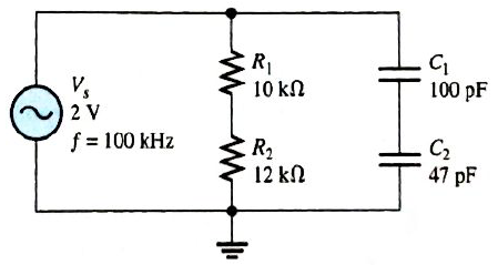
Convert the circuit in Figure 10-81 to an equivalent series form.
Expert Solution & Answer
Want to see the full answer?
Check out a sample textbook solution
Students have asked these similar questions
pls help in finding V0 in terms of Vi.
P
A DC voltage of 3V is applied across an RC series circuit. Voltage across
resistor is
When in forward biased, what have you noticed when you change the source voltage from 0V to +20V? When in reverse biased, what have you noticed when changing the source voltage from 0 V to -15V?
Chapter 10 Solutions
Electronics Fundamentals: Circuits, Devices & Applications
Ch. 10 - In a series RC circuit, the impedance increases...Ch. 10 - In a series RC lag circuit, the output voltage is...Ch. 10 - Admittance is the reciprocal of susceptance.Ch. 10 - In a parallel RC circuit, as frequency is...Ch. 10 - The phase angle of an RC circuit is measured...Ch. 10 - Prob. 6TFQCh. 10 - Prob. 7TFQCh. 10 - The power factor is equal to the tangent of the...Ch. 10 - A purely resistive circuit has a power factor of...Ch. 10 - Prob. 10TFQ
Ch. 10 - Prob. 1STCh. 10 - Prob. 2STCh. 10 - Prob. 3STCh. 10 - When the frequency of the voltage applied to a...Ch. 10 - Prob. 5STCh. 10 - Prob. 6STCh. 10 - The voltages in Problem 6 are measured at a...Ch. 10 - Prob. 8STCh. 10 - Prob. 9STCh. 10 - When the frequency of the source voltage is...Ch. 10 - Prob. 11STCh. 10 - Prob. 12STCh. 10 - Prob. 13STCh. 10 - Prob. 14STCh. 10 - If the bandwidth or a certain low-pass filter is 1...Ch. 10 - Prob. 1TSCCh. 10 - Prob. 2TSCCh. 10 - Prob. 3TSCCh. 10 - Determine the cause for each set of symptoms....Ch. 10 - Determine the cause for each set of symptoms....Ch. 10 - An 8 kHz sinusoidal voltage is applied to a series...Ch. 10 - What is th waveshape of the current in the circuit...Ch. 10 - Find the impedance of each circuit in Figure...Ch. 10 - Determine the impedance and the phase angle in...Ch. 10 - For the circuit of Figure 10-69, determine the...Ch. 10 - Repeat Problem 5 for C=0.0047F.Ch. 10 - Calculate the total current in each circuit of...Ch. 10 - Repeat Problem 7 for the circuits in Figure 10-68.Ch. 10 - For the circuit in Figure 10-70, draw the phase or...Ch. 10 - For the circuit in Figure 10-71, determine the...Ch. 10 - To what value must the rheostat be set in Figure...Ch. 10 - For the lag circuit in Figure 10-73, determine the...Ch. 10 - Repeat Problem 12 for the lead circuit in Figure...Ch. 10 - Determine the impedance for the circuit in Figure...Ch. 10 - Determine the impedance and the phase angle in...Ch. 10 - Repeat Problem 15 for the following frequencies:...Ch. 10 - Determine the impedance and phase angle in Figure...Ch. 10 - For the circuit in Figure 10-78, find all the...Ch. 10 - For the parallel circuit in Figure 10-79, find...Ch. 10 - For the circuit in Figu 10-80, determine the...Ch. 10 - Repeat Problem 20forR=4.7k,C=0.047F,andf=500Hz.Ch. 10 - Convert the circuit in Figure 10-81 to an...Ch. 10 - Determine the voltages across each element in...Ch. 10 - Is the circuit in Figure 10-82 predominantly...Ch. 10 - Find the current through each branch and the total...Ch. 10 - For the circuit in Figure 10-83, determine the...Ch. 10 - In a certain seris RC circuit, the true power is 2...Ch. 10 - In Figure 10-71, what is the true power and the...Ch. 10 - What is the power factor for the circuit of Figure...Ch. 10 - Determine Ptrue, Pr, Pa,andPF for the circuit in...Ch. 10 - The lag circuit in Figure 10-73 also acts as a...Ch. 10 - Plot the frequency response curve for the circuit...Ch. 10 - Draw the voltage phasor diagram for each circuit...Ch. 10 - Thr rms value of the signal voltage out of...Ch. 10 - Determine the cutoff frequency for each circuit in...Ch. 10 - Determine the bandwidth of the circuit in Figure...Ch. 10 - Assume that the capacitor in Figure 10-85 is...Ch. 10 - Each of the capacitors in Figure 10-86 has...Ch. 10 - Determine the output voltage for the circuit in...Ch. 10 - Determine the output voltage for the circuit in...Ch. 10 - A single 240V,60Hz source drives two loads. Load A...Ch. 10 - What value of coupling capacitor is required in...Ch. 10 - Determine the value of R1 required to get a phase...Ch. 10 - Draw the voltage and current phasor diagram for...Ch. 10 - A certain load dissipates 1.5kW of power with an...Ch. 10 - Deteine the series element or element that are in...Ch. 10 - Determine the value of C2 in Figure 10-91 when...Ch. 10 - Draw the schematic for the circuit in Figure 10-92...Ch. 10 - Open file P10-49; files are found at...Ch. 10 - Open file P10-50. Determine if there is a fault...Ch. 10 - www.prenhall.com/floyd. Open file P10-51....Ch. 10 - www.prenhall.com/floyd. Open file P10-52....Ch. 10 - www.prenhall.com/floyd. Open file P10-53....Ch. 10 - www.prenhall.com/floyd. Open file P10-54....
Knowledge Booster


Learn more about
Need a deep-dive on the concept behind this application? Look no further. Learn more about this topic, electrical-engineering and related others by exploring similar questions and additional content below.Similar questions
- An R-L series circuit contains two resistors and two inductors. The resistors dissipate powers of 96 watts and 125 watts. The inductors have reactive powers of 100 VARs and 78 VARs. What is the power factor?arrow_forwardA) find the current through each parallel branch in Figure below: A RUcin 17:5AL30- 112 H6 0000 60arrow_forwardseries circuitsarrow_forward
- The input voltage to chopper circuit with a switching frequency of 100 Hz and TOn time as 2.0 ms is 10 V. The average DC output is: O 4V O 2V O 6V O 8Varrow_forward1.Using the simulator of your choice simulate and screenshot the output voltage wave form for each circuit. +50 V R +5 V Vin Vout R- 47 0 3.3 kN Vin V out -50 V -5 V B Aarrow_forwardan rc series circuit is connected to a 120 v 60 hz power source the resistor is 25 ohm and has a voltage drop of 65 volts what is the capacitance of the capacitorarrow_forward
- (a) An AC triangular waveform with peak values of ±2V is used as an input to a comparator. The outputs of the comparator are VOH=+5V, VOL=-5V 4 Draw a waveform of the output of the comparator when an inverting circuit in Figure 5 is used. (i) Vi - 20 Vo 20 60 Figure 5arrow_forwarda capacitor and a resistor are connected in parellel to a 120 v 60 hz line the resistor has a resistance of 40 ohms and the capacitor has a capacitance of 132.6 uf what is the total current flow through the circuit. what is the impedence and the power factor and how many degrees out of phase are the current and voltage out phase with eachother.arrow_forwardparallel circuitarrow_forward
- In a series RC circuit the voltage across the capacitor and the resistor are 60 volts and 80 volts respectively. The total voltage isarrow_forwardA) What is the capacitor that must be added to this circuit to get a power factor of .90 600V 60HZ 10.8KW 8.2KVAR B) What is the total current Before the correction? C) What is the total current After the correction?arrow_forwardSolve this without using star delta conversion please it's importantarrow_forward
arrow_back_ios
SEE MORE QUESTIONS
arrow_forward_ios
Recommended textbooks for you
 Delmar's Standard Textbook Of ElectricityElectrical EngineeringISBN:9781337900348Author:Stephen L. HermanPublisher:Cengage Learning
Delmar's Standard Textbook Of Electricity
Electrical Engineering
ISBN:9781337900348
Author:Stephen L. Herman
Publisher:Cengage Learning
02 - Sinusoidal AC Voltage Sources in Circuits, Part 1; Author: Math and Science;https://www.youtube.com/watch?v=8zMiIHVMfaw;License: Standard Youtube License