
Introductory Circuit Analysis (13th Edition)
13th Edition
ISBN: 9780133923605
Author: Robert L. Boylestad
Publisher: PEARSON
expand_more
expand_more
format_list_bulleted
Concept explainers
Videos
Textbook Question
Chapter 10, Problem 40P
For the circuit in Fig. 10.108:
a. Find the time required for Uc to reach 48 V following the closing of the switch.
b. Calculate the current ic at the instant
c. Determine the power delivered by the source at the instant
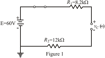
Fig. 10.108
Expert Solution & Answer
Want to see the full answer?
Check out a sample textbook solution
Students have asked these similar questions
A 2.62 ko resistor is connected to an AC voltage source with an rms voltage of 230 V.
(a) What is the maximum potential difference across the resistor (in V)?
V
(b) What is the maximum current through the resistor (in A)?
A
TOPIC: Fundamentals of Alternating Current Powers
Give illustration and a step by step solution. Final answer must be in 4 decimal places.
1. A load takes 55kW at 70% power factor lagging from a 240V, 50Hz supply. If the supply is made 60Hz, with the voltage remaining the same, what will be the kW load at 60Hz?
2. An inductive coil takes a current of 2A and consumes 160W when connected to a 240V supply. A second coil when connected across the same supply takes 3A and 500W. Find the total power when the two coils are connected in series to the supply.
3. A series RC circuit is connected to 230V, 60Hz source. If the power taken by the circuit is 4,800W and the voltage drop across the resistor is 115V, calculate the capacitance of the
capacitor.
Thank You in advance!
Thermal power plants classified according to prime mover and has the highest efficiency is
the combined cycle.
Select one:
O True
O False
Next page
cage
O Power system
General (Power Sys.
earch
Chapter 10 Solutions
Introductory Circuit Analysis (13th Edition)
Ch. 10 - a. Find the electric field strength at a point 1 m...Ch. 10 - The electric field strength is 72 newtons/coulomb...Ch. 10 - Find the capacitance of a parallel plate capacitor...Ch. 10 - How much charge is deposited on the plates of a...Ch. 10 - a. Find the electric field strength between the...Ch. 10 - A 6.8 pF parallel plate capacitor has 160 C of...Ch. 10 - Find the capacitance of a parallel plate capacitor...Ch. 10 - Repeat Problem 7 if the dielectric is...Ch. 10 - Find the distance in mils between the plates of a...Ch. 10 - The capacitance of a capacitor with a dielectric...
Ch. 10 - The plates of a parallel plate capacitor with a...Ch. 10 - A parallel plate air capacitor has a capacitance...Ch. 10 - Find the maximum voltage that can be applied...Ch. 10 - Find the distance in micrometers between the...Ch. 10 - A 22 pF capacitor has -200 ppm/C at room...Ch. 10 - What is the capacitance of a small teardrop...Ch. 10 - A large, flat, mica capacitor is labeled 471F....Ch. 10 - A small, flat, disc ceramic capacitor is labeled...Ch. 10 - For the circuit in Fig. 10.94, composed of...Ch. 10 - Repeat Problem 19 for R=100k, and compare the...Ch. 10 - For the circuit in Fig. 10.95, composed of...Ch. 10 - For the circuit in Fig. 10.96, composed of...Ch. 10 - Prob. 23PCh. 10 - The voltage across a 10 F capacitor in a series...Ch. 10 - For the R-C circuit in Fig. 10.97. composed of...Ch. 10 - For the network in Fig. 10.98. composed of...Ch. 10 - For the network in Fig.10.99.composed of standard...Ch. 10 - The 1000 F capacitor in Fig.10.100 is charged to...Ch. 10 - The capacitor in Fig. 10.101 is initially charged...Ch. 10 - Repeat Problem 29 if the initial charge is -40V.Ch. 10 - Repeat Problem 29 if the initial charge is +40V.Ch. 10 - The capacitor in Fig. 10.102 is initially charged...Ch. 10 - The capacitor in Fig. 10.103 is initially charged...Ch. 10 - The capacitor in Fig. 10.104 is initially charged...Ch. 10 - The capacitors of Fig. 10.105 are initially...Ch. 10 - Repeat Problem 35 if a 10 k resistor is placed in...Ch. 10 - Given the expression vc=140mV(1-e-t/2ms) a....Ch. 10 - For the automobile circuit of Fig. 10.106. VL must...Ch. 10 - Design the network in Fig.10.107 such that the...Ch. 10 - For the circuit in Fig. 10.108: a. Find the time...Ch. 10 - For the system in Fig. 10.109. using a DMM with a...Ch. 10 - For the circuit in Fig. 10.110: a. Find the...Ch. 10 - The capacitor in Fig. 10.111 is initially charged...Ch. 10 - The capacitors in Fig. 10.112 are initially...Ch. 10 - For the circuit in Fig. 10.113: a. Find the...Ch. 10 - The capacitor in Fig. 10.114 is initially charged...Ch. 10 - For the system in Fig. 10.115, using a DMM with a...Ch. 10 - Find the waveform for the average current if the...Ch. 10 - Find the waveform for the average current if the...Ch. 10 - Given the waveform in Fig.10.118 for the current...Ch. 10 - Find the total capacitance CT for the network in...Ch. 10 - Find the total capacitance CT for the network in...Ch. 10 - Find the steady-state voltage across and the...Ch. 10 - Find the steady-state voltage across and the...Ch. 10 - For the configuration in Fig. 10.123, determine...Ch. 10 - For the configuration in Fig.10.124, determine the...Ch. 10 - Find the energy stored by a 120 pF capacitor with...Ch. 10 - If the energy stored by a 6 F capacitor is 1200 J,...Ch. 10 - For the network in Fig. 10.125, determine the...Ch. 10 - An electronic flashgun has a 1000 F capacitor that...Ch. 10 - Using PSpice or Multisim, verify the results in...Ch. 10 - Using the initial condition operator, verify the...Ch. 10 - Using PSpice or Multisim, verify the results for...Ch. 10 - Using PSpice or Multisim, verify the results in...
Additional Engineering Textbook Solutions
Find more solutions based on key concepts
Does the severity of an electric shock increase ordecrease with eh of the following changes? a. A decrease in t...
Electric Motors and Control Systems
How many coulombs do 93.8 1016 electrons represent?
Principles Of Electric Circuits
Assume a telephone signal travels through a cable at two-thirds the speed of light. How long does it take the s...
Electric Circuits (10th Edition)
Identify the type of input and output configuration for each diff-amp in Figure 18-35.
Electronics Fundamentals: Circuits, Devices & Applications
The voltage source of the circuit shown in Fig. P1.29 is given by s(t)=25cos(4104t45)(V). Obtain an expression ...
Fundamentals of Applied Electromagnetics (7th Edition)
Analog Voltmeter Design Figure P2-98(a) shows a voltmeter circuit consisting of a D'Arsonval meter, two series ...
ANALYSIS+DESIGN OF LINEAR CIRCUITS(LL)
Knowledge Booster


Learn more about
Need a deep-dive on the concept behind this application? Look no further. Learn more about this topic, electrical-engineering and related others by exploring similar questions and additional content below.Similar questions
- 11. For the circuit below, determine the voltages across each component. 1k 50 mH50 nF 1 sin2pi1000t 1 cos2pi1000tarrow_forwardThe energy meter constant is given by (a) revolutions - Wh (b) revolutions – kWh (c) revolutions / Wh (d) revolutions /kWharrow_forwardFind the main current in the circuit in the figure ? ( 1 = ?) (consider complex numbers) 110 V/60 Hz/0 Deg 1 Ohm J 1 Ohm 1 Ohm -J10hm Ohmarrow_forward
- 1. Determine the peak voltage and the peak power delivered to R, in the following figure: 2:1 115 Vrms eeeee 00000 www RL 220 2arrow_forwardQI Us Using Time: 45 minule Noetal vocal analysis metheel, find current analysis All resistances in ohm, in each branch of the circuil. 8 De v 2 8 4 30 Varrow_forwardTMLINE 50 Hz( NEED NEAT HANDWRITTEN SOLUTION ONLY OTHERWISE DOWNVOTE).arrow_forward
- An alkaline fuel cell produces electricity as long as the fuel and oxidant are passed at the elecrodes. Select one: O True O Falsearrow_forwardThe meter constant of energy meter is given by revolutions/Wh. Select one: True Falsearrow_forwardA 200 load receives power from parallel-connected battery cells, as shown in the figure below. Determine the terminal voltage of the parallel- connected battery cells. r1 -r2 1 Ohm 1 Ohm -R_LOAD 20 Ohms V1 V2 12 V 12 V 11.6954 V 10.8875 V 11.7073 V 10.6543 V wwarrow_forward
- A generator supplies power to a factory through cables of total resistance 20 ohms. The potential difference at the generator is 5000 V and power output is 50 kW. Calculate (i) power suppled by the generator, (ii) potential difference at the factory.arrow_forwardA steam turbine generator is designed to generate 5.5MW of electrical power at a 6300V, 50HZ and 0.95 lag. The steam turbine requires 28 tons per hour of a high-pressure steam of temperature and pressure of 4000C and 40 bar. The steam turbine is a condensing type. If the temperature of the exhaust steam is 400 C (a).Calculate the efficiency of the steam turbine (b)What are the three (3) major advantages and disadvantages of the steam turbine? (c )What are the methods of improving efficiency of the Brayton cycle?arrow_forwardCircuits 1 HW 6 Q3arrow_forward
arrow_back_ios
SEE MORE QUESTIONS
arrow_forward_ios
Recommended textbooks for you
 Introductory Circuit Analysis (13th Edition)Electrical EngineeringISBN:9780133923605Author:Robert L. BoylestadPublisher:PEARSON
 Delmar's Standard Textbook Of ElectricityElectrical EngineeringISBN:9781337900348Author:Stephen L. HermanPublisher:Cengage Learning
 Programmable Logic ControllersElectrical EngineeringISBN:9780073373843Author:Frank D. PetruzellaPublisher:McGraw-Hill Education
 Fundamentals of Electric CircuitsElectrical EngineeringISBN:9780078028229Author:Charles K Alexander, Matthew SadikuPublisher:McGraw-Hill Education
 Electric Circuits. (11th Edition)Electrical EngineeringISBN:9780134746968Author:James W. Nilsson, Susan RiedelPublisher:PEARSON
 Engineering ElectromagneticsElectrical EngineeringISBN:9780078028151Author:Hayt, William H. (william Hart), Jr, BUCK, John A.Publisher:Mcgraw-hill Education,
Introductory Circuit Analysis (13th Edition)
Electrical Engineering
ISBN:9780133923605
Author:Robert L. Boylestad
Publisher:PEARSON
Delmar's Standard Textbook Of Electricity
Electrical Engineering
ISBN:9781337900348
Author:Stephen L. Herman
Publisher:Cengage Learning
Programmable Logic Controllers
Electrical Engineering
ISBN:9780073373843
Author:Frank D. Petruzella
Publisher:McGraw-Hill Education
Fundamentals of Electric Circuits
Electrical Engineering
ISBN:9780078028229
Author:Charles K Alexander, Matthew Sadiku
Publisher:McGraw-Hill Education
Electric Circuits. (11th Edition)
Electrical Engineering
ISBN:9780134746968
Author:James W. Nilsson, Susan Riedel
Publisher:PEARSON
Engineering Electromagnetics
Electrical Engineering
ISBN:9780078028151
Author:Hayt, William H. (william Hart), Jr, BUCK, John A.
Publisher:Mcgraw-hill Education,
Capacitors Explained - The basics how capacitors work working principle; Author: The Engineering Mindset;https://www.youtube.com/watch?v=X4EUwTwZ110;License: Standard YouTube License, CC-BY