
Applied Statics and Strength of Materials (6th Edition)
6th Edition
ISBN: 9780133840544
Author: George F. Limbrunner, Craig D'Allaird, Leonard Spiegel
Publisher: PEARSON
expand_more
expand_more
format_list_bulleted
Concept explainers
Videos
Textbook Question
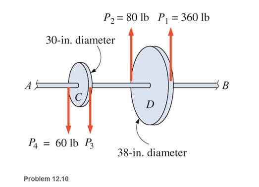
Chapter 12, Problem 12.10P
Pulleys C and D are attached to shaft AB, as shown. The shaft is supported on bearings at each end. The shaft rotates at a uniform speed. Pulley D is the driver and pulley C is the power take-off. The diameter of the shaft is 2
a. the belt tension
b. the maximum shear stress in the shaft.
Expert Solution & Answer
Want to see the full answer?
Check out a sample textbook solution
Students have asked these similar questions
A bevel gear is attached to a shaft supported by self-aligning bearings at A and B and is driven by a motor. The axial force, radial force, and tangential force are known. Assume the weight of the gear and shaft is negligible and that the bearing at A takes all the thrust load
A) Draw (to scale) axial load, shaft torque, shear force(x-y and x-z), and bending moment(x-y and x-z)diagrams for the shaft
B)Determine the values of axial load and torque along the shaft
3. A steel shaft 60 in. long has applied to it a 10,000 in-lb torque by a pulley located at the center
of the shaft. A gear at the left end of the shaft applies 8000 in-lb of torque to the shaft while a
gear located 9 in. to the left of the right end of the shaft applies 2000 in-lb of torque. Calculate
the angular deflection of the shaft if the shaft is 2 in. in diameter for a length of 36 in. from the
left end of the shaft and 1.5 in. in diameter in the remainder of the shaft. Neglect the effect of the
keyways in the calculations.
Ans. 0.424o
Determine the resisting torque at support A and B , of the shaft shown in the figure.
Chapter 12 Solutions
Applied Statics and Strength of Materials (6th Edition)
Ch. 12 - Determine the internal resisting torque in the...Ch. 12 - Determine the internal resisting torque in the...Ch. 12 - Calculate the maximum shear stress developed in a...Ch. 12 - Calculate the allowable torque for a hollow steel...Ch. 12 - Calculate the allowable torque that may be applied...Ch. 12 - A hollow circular steel shaft has a 100-mm outside...Ch. 12 - Design a solid circular steel shaft to transmit an...Ch. 12 - Calculate the shear stresses at the outer and...Ch. 12 - A hollow shaft is produced by boring a...Ch. 12 - Pulleys C and D are attached to shaft AB, as...
Ch. 12 - Calculate the angle of twist a 3-in-diameter...Ch. 12 - Calculate the angle of twist a 65-mm-diameter...Ch. 12 - Calculate the angle of twist a 4-in.-diameter...Ch. 12 - Prob. 12.14PCh. 12 - Prob. 12.15PCh. 12 - A solid steel shaft is to resist a torque of 9000...Ch. 12 - A hollow steel shaft has a 50-mm outside diameter...Ch. 12 - If the shaft of Problem 12.17 were solid, with the...Ch. 12 - An automobile engine develops 90 hp at 3500 rpm....Ch. 12 - Calculate the speed (rpm) at which a...Ch. 12 - Select the diameter of a solid circular steel...Ch. 12 - Select the diameter for a hollow steel shaft that...Ch. 12 - A 6-ft-long solid steel shaft with a diameter of 4...Ch. 12 - The outside and inside diameters of a hollow steel...Ch. 12 - Calculate the maximum shear stress developed in a...Ch. 12 - Write a program that will calculate the allowable...Ch. 12 - Write a program that will generate a table of...Ch. 12 - Rework the program of Problem 12.27 using SI...Ch. 12 - Write a program that will generate a table of...Ch. 12 - Compute the maximum shear stress in the hollow...Ch. 12 - Calculate the allowable torque that may be applied...Ch. 12 - Design a hollow steel shaft to transmit a torque...Ch. 12 - A 32-in.-long solid steel circular shaft, 3 in. in...Ch. 12 - The 65-mm-diameter solid shaft shown is subjected...Ch. 12 - Rework Problem 12.34, changing the diameter of...Ch. 12 - Compute the maximum shear stress in the circular...Ch. 12 - Determine the allowable torque a hollow steel...Ch. 12 - A 1.00-m-long steel wire, 4 mm in diameter, is...Ch. 12 - Select the outside and inside diameters for a...Ch. 12 - A solid aluminum shaft, 6 ft in length, is to...Ch. 12 - A 25-mm-diameter solid shaft with an allowable...Ch. 12 - Compute a. the maximum shear stress developed in a...Ch. 12 - What horsepower can a solid steel shaft 6 in. in...Ch. 12 - Calculate the maximum power that may be...Ch. 12 - A small ski lift has a main cable driving wheel 11...Ch. 12 - A 32-mm-diameter solid shaft transmits 100 kW of...Ch. 12 - A solid steel shaft is to transmit power of 58 kW...Ch. 12 - Select the diameter for a solid steel shaft that...Ch. 12 - A solid steel shaft is to transmit 100 hp at a...Ch. 12 - Two shafts-one a hollow steel shaft with an...Ch. 12 - A 112 -in.-diameter solid steel shaft is 40 ft in...Ch. 12 - A solid steel shaft is to transmit 120 hp. The...
Knowledge Booster


Learn more about
Need a deep-dive on the concept behind this application? Look no further. Learn more about this topic, mechanical-engineering and related others by exploring similar questions and additional content below.Similar questions
- thick lnange be! The total torque required to turn the double threaded power screw is 55 N.m. If the screw turns at 285 rpm and the pitch of 4mm, find: A. The horsepower input of the power screw. B. The efficiency if the weight loaded is 10 kN.arrow_forwardFor the shaft shown in the figure below, compute the angle of twist of pulleys B and C relative to A. The steel shaft has a diameter of 35 mm throughout its length. The torques are T1= 1500 N · m, T2 = 1000 N · m, = 500 N · m. The lengths are L, = 500 mm, L2 = 800 mm. T3 L2 T |T2 T3 A C B.arrow_forward2. A composite shaft is made of slipping a bronze tube of 3-in. outer diameter and 2-in. inner diameter over a solid steel shaft of the same length and 2-in. diameter. The two components are fastened rigidly together at their ends. What is the largest torque that can be carried by the composite shaft if the working shear stresses are 10 ksi for bronze and 14 ksi for the steel? If the hollow tube is made out of steel and the solid shaft is made out of bronze, what is the largest torque that can be carried by the composite shaft if the same working shear stresses are applied? For bronze, G = 6 x 10° psi, and for steel, G = 12 x 10°.arrow_forward
- A transmission shaft supporting a helical gear B and an overhung bevel gear D is shown in Fig. bearings, A and C. The pitch circle diameter of the helical gear is 450 mm and the diameter of the bevel gear at the forces is 450 mm. Power is transmitted from the helical gear to the bevel gear. The gears are keyed to the shaft. The material of the shaft is steel 45C8 The factors k, and k, of ASME code are 2.0 and 1.5 respectively. Determine the shaft diameter using the ASME code. 400 The shaft is mounted on two 400 400 270 250 210 640i ]640 100arrow_forward1) The rotating solid steel shaft (Fig.1 a) is simply supported by bearings at points B and C and is driven by a gear (not shown) which meshes with the spur gear at D, which has a 150 mm pitch diameter. The force F from the drive gear acts at a pressure angle of 20°. The shaft transmits a torque to point “A" of TA = 300 N.m. There is a step at point "C" as shown in Fig.1 (b), assume that D/d ratio is 1,09 and fillet radius (r) is 2,5 mm. a) Find the stress concentrations at point "C" due to bending and shear loads (Initially assume d=50mm). If the shaft is machined from quenched and drawn steel with Sy= 420 MPa and Sut=560 MPa and b) using a factor of safety of 2.5, determine the minimum allowable diameter of the shaft at "C" based on a static yield analysis using the distortion energy (DE) theory. If the shaft with a diameter (d) of 32 mm is made of a brittle material with Suc = 420 MPa and c) Sut=360 MPa, determine the factor of safety of the shaft at "C" based on a static analysis…arrow_forward4) The 1.5 in diameter shaft below is supported by a thrust bearing at A and a self-aligning bearing at B. The gear weights 100 lbs and supports a 400 lb load in the axial direction (+x-direction), a 2000 lb transmitted load (+y-direction), and 600 lb radial load (-z-direction). The pulley weighs 400 lb and supports loads in the +z-direction. a. Construct the V-M-N-T diagrams for the shaft. b. Determine the location on the shaft with the most severe state of stress. c. Sketch the Mohr's circle and find the principal stresses at that location. 6 in. -12 in. - 8 in. YA 400 lb 600 lb Gear 2000 lb 4 in. 1200 lb 200 lb D 8 in. Pulleyarrow_forward
- 1. The rotating solid steel shaft is simply supported by bearings at points B and C and is driven by a gear (not shown) which meshes with the spur gear at D, which has a 150-mm pitch diameter. The force F from the driver gear acts at a pressure angle of 20 degree. The shaft transmits a torque to point A of TA =340 N.m. The shaft is machined from steel with S,=420 MPa, Km2.5, S=134MPA and N=2. Draw shear and bending diagrams and calculate diameter of shaft. 250 mm 100 mmarrow_forward1. The endurance limit for rotating shaft, if its ultimate strength Su=1600 Mpa is:arrow_forwardThe rotating solid steel shaft is simply supported by bearings at points B and C and is driven by a gear (not shown) which meshes with the spur gear at D, which has a 140-mm pitch diameter. The force F from the drive gear acts at a pressure angle of 20°. The shaft transmits a torque to point A of TA = 260 N-m. The shaft is machined from steel with Sy = 400 MPa and Sut = 560 MPa. Assume factor of safety and all other factors as (one) 1,. Determine the minimum allowable diameter of the 100-mm section of the shaft for infinite life (selectec criter sould be written at the begining of the solution) 250 mm 100 mm 20arrow_forward
- The end of a 2.5 in diameter steel shaft is milled to two flats (one flat on the top and one flat at the bottom) to permit the use of a hand crank. Each flat is located 1.00 in from the center of the shaft. A torque of 750 Ib-in is applied. Find: (a) the maximum shear stress at the end of the shaft with two flats in psi unit. (b) the angle of twist in fadians (c) the angle of twist in degrees h= 1.0 in h= 1.0 in d= 2.50 in Show all your calculations.arrow_forwardEx: The second shaft on a parallel-shaft 25-hp foundry crane speed reducer contains a helical gear with a pitch diameter of S.08 in. Helical gears transmit components of force in the tangential, radial, and axial directions. The components of the gear force transmitted to the second shaft are shown in Fig. (8) at point A. The bearing reactions at C and D, assuming simple- supports, are also shown. A ball bearing is to be selected for location C to accept the thrust, and a cylindrical roller bearing is to be utilized at location D. The life goal of the speed reducer is 10 kh, with a reliability factor for the ensemble of all four bearings (both shafts) to equal 1 (90% reliability) with light to moderate impact. (a) Select the roller bearing for location D. (b) Select the ball bearing (angular contact) for location C, assuming the inner ring rotates. *- 20 Fig (8)arrow_forwarda) A line shaft as shown in Figure Q is driven using a motor placed vertically below it. The pulley on the line shaft is 1.6 m in diameter and has belt tensions 7.5 kN and 2.4 kN on the tight side and slack side of the belt respectively. Both tensions may be assumed to be vertical and the weight of the pulley is negligible. If the pulley is overhang from the shaft, the distance of the centre line of the pulley from the centre line of the bearing being 500 mm.6.Figure Q(i) Predict using distortion energy theory, the appropriate diameter of the shaft that failure will not occur if the yield strength, Sy = 370 Mpa and factor of safety is 2.5. (ii) Assuming the maximum allowable shear stress of 42 MPa, find its diameter using maximum shear stress theory. (iii) Comparing the diameters in (i) and (iii) above, which of them would you have used to design your shaft and why?arrow_forward
arrow_back_ios
SEE MORE QUESTIONS
arrow_forward_ios
Recommended textbooks for you
 Mechanics of Materials (MindTap Course List)Mechanical EngineeringISBN:9781337093347Author:Barry J. Goodno, James M. GerePublisher:Cengage Learning
Mechanics of Materials (MindTap Course List)
Mechanical Engineering
ISBN:9781337093347
Author:Barry J. Goodno, James M. Gere
Publisher:Cengage Learning
EVERYTHING on Axial Loading Normal Stress in 10 MINUTES - Mechanics of Materials; Author: Less Boring Lectures;https://www.youtube.com/watch?v=jQ-fNqZWrNg;License: Standard YouTube License, CC-BY