
Loose Leaf for Engineering Circuit Analysis Format: Loose-leaf
9th Edition
ISBN: 9781259989452
Author: Hayt
Publisher: Mcgraw Hill Publishers
expand_more
expand_more
format_list_bulleted
Concept explainers
Videos
Textbook Question
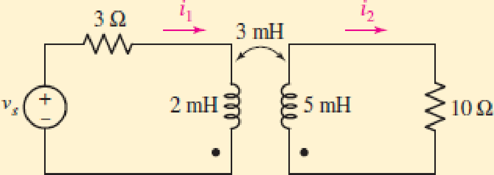
Chapter 13.1, Problem 3P
For the circuit of Fig. 13.11, write an appropriate mesh equation in terms of the phasor currents I1 and I2 for the (a) left mesh; (b) right mesh.
FIGURE 13.11
Expert Solution & Answer
Want to see the full answer?
Check out a sample textbook solution
Students have asked these similar questions
termine the phasor currents Iy and I, in the circuit of Fig. 13.13. 5Q j2 AMN—TIT Q . 3Q 20460°v. @ éjéfl @ = -j4Q . ey Figure 13.13 For Practice Prob. 13.2.
Short Problem: Given a series circuit comprised of the following element: 92.15-ohm resistor, practical inductor with internal resistance of 0.27 ohm and reactance of 50.73 ohms; and a capacitor with reactance of 19.03 ohms. Compute for the magnitude of its equivalent impedance in ohms.
Note: Follow this reminder carefully. Compute to the nearest 4 decimal places. No Scientific notation. Do not round off in the middle of calculation. Use stored values. Write the numerical values only. No units in your final answer. Spaces are not allowed. Excessive number of decimals as
compared to the required number of decimals may result to an incorrect answer.
A 300 m ring distributor has loads as shown in Fig. 13.45 where distances are in metres. The resistance of each conductor is 0·2 W per 1000 metres and the loads are tapped off at points B, C and D asshown. If the distributor is fed at A at 240 V, find voltages at B, C and D
Chapter 13 Solutions
Loose Leaf for Engineering Circuit Analysis Format: Loose-leaf
Ch. 13.1 - Assuming M = 10 H, coil L2 is open-circuited, and...Ch. 13.1 - For the circuit of Fig. 13.9, write appropriate...Ch. 13.1 - For the circuit of Fig. 13.11, write an...Ch. 13.2 - Let is = 2 cos 10t A in the circuit of Fig. 13.14,...Ch. 13.3 - Element values for a certain linear transformer...Ch. 13.3 - (a) If the two networks shown in Fig. 13.20 are...Ch. 13.3 - If the networks in Fig. 13.23 are equivalent,...Ch. 13.4 - Prob. 8PCh. 13.4 - Let N1 = 1000 turns and N2 = 5000 turns in the...Ch. 13 - Prob. 1E
Ch. 13 - With respect to Fig. 13.36, assume L1 = 500 mH, L2...Ch. 13 - The circuit in Fig. 13.36 has a sinusoidal input...Ch. 13 - Prob. 4ECh. 13 - Prob. 5ECh. 13 - The circuit in Fig. 13.38 has a sinusoidal input...Ch. 13 - The physical construction of three pairs of...Ch. 13 - Prob. 8ECh. 13 - Prob. 9ECh. 13 - Calculate v1 and v2 if i1 = 5 sin 40t mA and i2 =...Ch. 13 - Prob. 11ECh. 13 - For the circuit of Fig. 13.41, calculate I1, I2,...Ch. 13 - Prob. 13ECh. 13 - Prob. 14ECh. 13 - In the circuit of Fig. 13.43, M is reduced by an...Ch. 13 - Prob. 16ECh. 13 - Prob. 17ECh. 13 - Prob. 18ECh. 13 - Prob. 19ECh. 13 - Note that there is no mutual coupling between the...Ch. 13 - Prob. 21ECh. 13 - (a) Find Zin(j) for the network of Fig 13.50. (b)...Ch. 13 - For the coupled coils of Fig. 13.51, L1 = L2 = 10...Ch. 13 - Prob. 24ECh. 13 - Prob. 25ECh. 13 - Prob. 26ECh. 13 - Consider the circuit represented in Fig. 13.53....Ch. 13 - Compute v1, v2, and the average power delivered to...Ch. 13 - Assume the following values for the circuit...Ch. 13 - Prob. 30ECh. 13 - Prob. 31ECh. 13 - Prob. 32ECh. 13 - Prob. 33ECh. 13 - Prob. 34ECh. 13 - Prob. 35ECh. 13 - Prob. 36ECh. 13 - Prob. 37ECh. 13 - FIGURE 13.60 For the circuit of Fig. 13.60, redraw...Ch. 13 - Prob. 39ECh. 13 - Prob. 40ECh. 13 - Calculate the average power delivered to the 400 m...Ch. 13 - Prob. 42ECh. 13 - Calculate the average power delivered to each...Ch. 13 - Prob. 44ECh. 13 - Prob. 45ECh. 13 - Prob. 46ECh. 13 - Prob. 47ECh. 13 - Prob. 48ECh. 13 - A transformer whose nameplate reads 2300/230 V, 25...Ch. 13 - Prob. 52ECh. 13 - As the lead singer in the local rock band, you...Ch. 13 - Obtain an expression for V2/Vs in the circuit of...Ch. 13 - Prob. 55E
Additional Engineering Textbook Solutions
Find more solutions based on key concepts
Identify the type of input and output configuration for each diff-amp in Figure 18-35.
Electronics Fundamentals: Circuits, Devices & Applications
How many coulombs do 93.8 1016 electrons represent?
Principles Of Electric Circuits
Three point charges of equal magnitude q, that will yield a zero net electric field at the origin.
Engineering Electromagnetics
Write the nodal equations for the network of Fig. 8.137 using the general approach. Find the nodal voltages usi...
Introductory Circuit Analysis (13th Edition)
Find I0 and I1 in the circuit in Fig.P2.12.
Basic Engineering Circuit Analysis
Design an ideal inverting op-amp circuit such that the voltage gain is Av=25 . The maximum current in any resis...
Microelectronics: Circuit Analysis and Design
Knowledge Booster


Learn more about
Need a deep-dive on the concept behind this application? Look no further. Learn more about this topic, electrical-engineering and related others by exploring similar questions and additional content below.Similar questions
- Short Problem: Given a series circuit comprised of the following element: 65.7-ohm resistor, practical inductor with internal resistance of 0.94 ohm and reactance of 62.58 ohms; and a capacitor with reactance of 18.82 ohms. Compute for equivalent impedance angle in degrees. Note: Follow this reminder carefully. Compute to the nearest 4 decimal places. No Scientific notation. Do not round off in the middle of calculation. Use stored values. Write the numerical values only. No units in your final answer. Spaces are not allowed. Excessive number of decimals as compared to the required number of decimals may result to an incorrect answer.arrow_forwardGiven a series circuit comprised of the following element: 92.61-ohm resistor, practical inductor with internal resistance of 0.6 ohm and reactance of 78.43 ohms; and a capacitor with reactance of 7.55 ohms. Compute for the magnitude of its equivalent impedance in ohms. Compute to the nearest 4 decimal places. No Scientific notation. Do not round off in the middle of calculation.arrow_forwardWhich can be said according to the circuit and phasor diagram given below? A) Impedance of circuit element 3 is greater than impedance of circuit element 2. B) The active power of the element 2 is greater than the total active power of the elements 3 and 5. C) The average power of element 4 is zero D) The current of element 2 is less than the total current flowing through circuit elements 3 and 5.arrow_forward
- Given a series circuit comprised of the following element: 82.4-ohm resistor, practical inductor with internal resistance of 0.95 ohm and reactance of 61.11 ohms; and a capacitor with reactance of 18.69 ohms. Compute for the magnitude of its equivalent impedance in ohms. Compute to the nearest 4 decimal places. No Scientific notation. Do not round off in the middle of calculation. Use stored values.arrow_forwardA coil of inductance 159.2mH and resistance 20ohms is connected in series with a 60ohms resistor to a 240V, 50HZ supply. Determine a) the impedance of the circuit, b) the current in the circuit, c) the circuit phase angle, d) the p.d. difference across the resistor and the coil, e) draw the circuit phasor diagram showing all voltages.arrow_forwardGiven a series circuit comprised of the following element: 81.59-ohm resistor, practical inductor with internal resistance of 0.99 ohm and reactance of 54.29 ohms; and a capacitor with reactance of 6.15 ohms. Compute for equivalent impedance angle in degrees. Note: Follow this reminder carefully. Compute to the nearest 4 decimal places. No Scientific notation. Do not round off in the middle of calculation. Use stored values. Write the numerical values only. No units in your final answer. Spaces are not allowed. Excessive number of decimals as compared to the required number of decimals may result to an incorrect answer.arrow_forward
- 13. A coil has a resistance of 6 ohms and an inductance of 0.02 H. When a non-inductive resistor is connected in series with the coil, the current drawn when connected to a 220 V DC source is equal to the current drawn by the coil alone across a 220 V, 60 Hz source. Determine the resistance of the non- inductive resistor. A) 3.63 0 B. 6.39 N C. 3.69 N D. 3.96 Narrow_forwardGiven a series circuit comprised of the following element: 77.03-ohm resistor, practical inductor with internal resistance of 0.16 ohm and reactance of 74.36 ohms; and a capacitor with reactance of 12.45 ohms. Compute for the magnitude of its equivalent impedance in ohms. Note: Follow this reminder carefully. Compute to the nearest 4 decimal places. No Scientific notation. Do not round off in the middle of calculation. Use stored values.arrow_forwardGiven a series circuit comprised of the following element: 85.45-ohm resistor, practical inductor with internal resistance of 0.38 ohm and reactance of 66.42 ohms; and a capacitor with reactance of 6.59 ohms. Compute for equivalent impedance angle in degrees. Compute to the nearest 4 decimal places. No Scientific notation. Do not round off in the middle of calculation. Use stored values.arrow_forward
- The resistance and inductance oOf the impedance coll Item : TLO #: TLO 1 When an impedance coil is connected to a 100 V. 60-Hz, ac supply, the circuit current is 1.325 A. When it is connected to a 100 V, 30-Hz, ac supply, the circuit current is 1.741 A. Find the resistance and the inductance of the impedance coil.arrow_forwardShort Problem: Given a parallel RLC circuit comprised of the following element: 55.27-ohm resistor, ideal inductor with reactance of 33.87 ohms; and a capacitor with reactance of 14.68 ohms. Compute for reactive power in VArs given an ac voltage source of 100 cis 0 volts. Give only the absolute value. Note: Follow this reminder carefully. Compute to the nearest 4 decimal places. No Scientific notation. Do not round off in the middle of calculation. Use stored values. Write the numerical values only. No units in your final answer. Spaces are not allowed. Excessive number of decimals as compared to the required number of decimals may result to an incorrect answer.arrow_forwardGiven a series circuit comprised of the following element: 65.97-ohm resistor, practical inductor with internal resistance of 0.53 ohm and reactance of 48.76 ohms; and a capacitor with reactance of 14.32 ohms. Compute for the magnitude of its equivalent impedance in ohms. Round off your final answer to the nearest 4 decimal places. No Scientific notation. Do not round off in the middle of calculation. Use stored values.arrow_forward
arrow_back_ios
SEE MORE QUESTIONS
arrow_forward_ios
Recommended textbooks for you
 Introductory Circuit Analysis (13th Edition)Electrical EngineeringISBN:9780133923605Author:Robert L. BoylestadPublisher:PEARSON
 Delmar's Standard Textbook Of ElectricityElectrical EngineeringISBN:9781337900348Author:Stephen L. HermanPublisher:Cengage Learning
 Programmable Logic ControllersElectrical EngineeringISBN:9780073373843Author:Frank D. PetruzellaPublisher:McGraw-Hill Education
 Fundamentals of Electric CircuitsElectrical EngineeringISBN:9780078028229Author:Charles K Alexander, Matthew SadikuPublisher:McGraw-Hill Education
 Electric Circuits. (11th Edition)Electrical EngineeringISBN:9780134746968Author:James W. Nilsson, Susan RiedelPublisher:PEARSON
 Engineering ElectromagneticsElectrical EngineeringISBN:9780078028151Author:Hayt, William H. (william Hart), Jr, BUCK, John A.Publisher:Mcgraw-hill Education,
Introductory Circuit Analysis (13th Edition)
Electrical Engineering
ISBN:9780133923605
Author:Robert L. Boylestad
Publisher:PEARSON
Delmar's Standard Textbook Of Electricity
Electrical Engineering
ISBN:9781337900348
Author:Stephen L. Herman
Publisher:Cengage Learning
Programmable Logic Controllers
Electrical Engineering
ISBN:9780073373843
Author:Frank D. Petruzella
Publisher:McGraw-Hill Education
Fundamentals of Electric Circuits
Electrical Engineering
ISBN:9780078028229
Author:Charles K Alexander, Matthew Sadiku
Publisher:McGraw-Hill Education
Electric Circuits. (11th Edition)
Electrical Engineering
ISBN:9780134746968
Author:James W. Nilsson, Susan Riedel
Publisher:PEARSON
Engineering Electromagnetics
Electrical Engineering
ISBN:9780078028151
Author:Hayt, William H. (william Hart), Jr, BUCK, John A.
Publisher:Mcgraw-hill Education,
TRANSFORMERS - What They Are, How They Work, How Electricians Size Them; Author: Electrician U;https://www.youtube.com/watch?v=tXPy4OE7ApE;License: Standard Youtube License