
University Physics Volume 2
18th Edition
ISBN: 9781938168161
Author: OpenStax
Publisher: OpenStax
expand_more
expand_more
format_list_bulleted
Concept explainers
Textbook Question
Chapter 14, Problem 56P
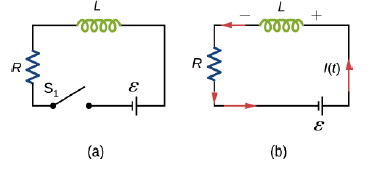
Examine the circuit shown below in part (a). Determine dl/dt at the instant after the switch is thrown in the circuit of (a), thereby producing the circuit of (b). Show that if I were to continue to increase at this initial rate, It would reach its maximum
Expert Solution & Answer
Want to see the full answer?
Check out a sample textbook solution
Students have asked these similar questions
Examine the circuit shown below in part (a). Determine dI/dt at the instant after the switch is thrown in the circuit of (a), thereby producing the circuit of (b). Show that if I were to continue to increase at this initial rate, it would reach its maximum ε/R in one time constant.
The remaining circuit quantities may change instantaneously as required by Kirchhoff's rules. Q in uC immediately after the switch ( t = 0 + ), in that order.
Problem 2: The values for the components of the circuit shown in the figure are V= 12 V, C =
4.2 µF, and L = 190 mH. When the capacitor is fully charged, you simultaneously open switch S, and
close switch S2-
C
Part (a) Find the frequency of the resulting oscillations, in hertz.
f =
sin()
cos()
tan()
8
НОМE
cotan()
asin()
acos()
4
5
6.
atan()
acotan()
sinh()
1
2
tanh()
ODegrees O Radians
cosh()
cotanh()
END
vol BACKSPACE DEL CLEAR
Submit
Hint
Feedback
I give up!
Part (b) What is the maximum charge on the capacitor, in coulombs, during the oscillations?
Part (c) Find the maximum current through the inductor, in amperes, during the oscillations.
Part (d) What is the electromagnetic energy of the oscillating circuit, in joules?
Chapter 14 Solutions
University Physics Volume 2
Ch. 14 - Check Your Understanding. A current...Ch. 14 - Check Your Understanding. Current flows through...Ch. 14 - Check Your Understanding. A changing current...Ch. 14 - Check Your Understanding (a) Calculate the...Ch. 14 - Check Your Understanding (a) What is the magnetic...Ch. 14 - Check Your Understanding How much energy is stored...Ch. 14 - Check Your Understanding Verify that RC and L/R...Ch. 14 - Check Your Understanding (a) If the current in the...Ch. 14 - Check Your Understanding For the circuit of in...Ch. 14 - Check Your Understanding The angular frequency of...
Ch. 14 - Check Your Understanding In an RLC circuit, L =...Ch. 14 - Show that N m /l and el(dl/dt), which are both...Ch. 14 - A 10-H inductor carries a current of 20 A....Ch. 14 - The ignition circuit of an automobile is powered...Ch. 14 - When the current through a large inductor is...Ch. 14 - Does self-inductance depend on the value of the...Ch. 14 - Would the self-inductance of a 1.0 m long, tightly...Ch. 14 - Discuss how you might determine the-inductance per...Ch. 14 - The self-inductance of a coil is zero if there is...Ch. 14 - How does the self- inductance per unit length near...Ch. 14 - Solve that I I 2 /2 has units of energy.Ch. 14 - Use Lenz’s law to explain why the initial current...Ch. 14 - When the current in the RL circuit of Figure...Ch. 14 - Does the time required for the current in an RL...Ch. 14 - An inductor is connected across the terminals of a...Ch. 14 - At what time is the voltage across the inductor of...Ch. 14 - In the simple RL circuit of Figure 14.12(b), can...Ch. 14 - If emf of the battery of Figure 14.12(b) is...Ch. 14 - A steady current flows through a circuit with a...Ch. 14 - Describe how the currents through R1and R2, shown...Ch. 14 - Discuss possible practical applications of RL...Ch. 14 - Do Kirchhoff’s rules apply to circuits that...Ch. 14 - Can a circuit e1eent have both capacitance and...Ch. 14 - In an LC circuit, what determines the frequency...Ch. 14 - When a wire is connected between the two ends of a...Ch. 14 - Describe what effect the resistance of the...Ch. 14 - Suppose you wanted to design an LC circuit with a...Ch. 14 - A radio receiver uses an RLC circuit to pick out...Ch. 14 - When the current in one coi1 changes at a rate of...Ch. 14 - An emf of 9.7 × 10⁻³ V is induced in a coil while...Ch. 14 - Two coils close to each other have a mutual...Ch. 14 - A coil of 40 turns is wrapped around a long...Ch. 14 - A 600-turn solenoid is 0.55 m long and 4.2 cm in...Ch. 14 - A toroidal coil has a mean radius of 16 cm and a...Ch. 14 - A solenoid of N1turns has length l1and radius R1,...Ch. 14 - An emf of 0.40 V is induced across a coil when the...Ch. 14 - The current shown in part (a) below is increasing,...Ch. 14 - What is the rate at which the current though a...Ch. 14 - When a camera uses a flash, a fully charged...Ch. 14 - A coil with a self-inductance of 2.0 H carries a...Ch. 14 - A solenoid 50 cm long is wound with 500 turns of...Ch. 14 - A coil with a self-inductance of 3.0 H carries a...Ch. 14 - The current I(t) through a 5.0-mH inductor varies...Ch. 14 - A long, cylindrical solenoid with 100 turns per...Ch. 14 - Suppose that a rectangular toroid has 2000...Ch. 14 - What is the self-inductance per meter of a coaxial...Ch. 14 - At the instant a current of 0.20 A is flowing...Ch. 14 - Suppose that a rectangular toroid has 2000...Ch. 14 - Solenoid A is tightly wound while solenoid B has...Ch. 14 - A 10-H inductor carries a current of 20 A. How...Ch. 14 - A coil with a self-inductance of 3.0 H and a...Ch. 14 - A current of 1.2 A is flowing in a coaxial cable...Ch. 14 - In Figure 14.12, =12V , L = 20 mH, and R=5.0....Ch. 14 - For the circuit shown below, =20V , L = 4.0 mH,...Ch. 14 - The current in the RL circuit shown here increases...Ch. 14 - How long after switch S1 is thrown does it take...Ch. 14 - Examine the circuit shown below in part (a)....Ch. 14 - The current in the RL circuit shown below reaches...Ch. 14 - Consider the circuit shown below. Find l1, l2and...Ch. 14 - For the circuit shown below, =50V , R1= 10 , and...Ch. 14 - For the circuit shown below, find the current...Ch. 14 - Show that for the circuit shown below, the initial...Ch. 14 - A 5000-pF capacitor is charged to 100 V and then...Ch. 14 - The self-inductance and capacitance of an LC...Ch. 14 - What is the self-inductance of an LC circuit that...Ch. 14 - In an oscillating LC circuit the maximum charge on...Ch. 14 - The self-inductance and capacitance of an...Ch. 14 - In an oscillating LC circuit, the maximum charge...Ch. 14 - In the circuit shown below, S1is opened and S2is...Ch. 14 - An LC circuit in an AM tuner (in a car stereo)...Ch. 14 - In an oscillating RLC circuit, R=5.0 ,. L=5.0mH ,...Ch. 14 - In an oscillating RLC circuit with L = 10 mH, C =...Ch. 14 - What resistance R must be connected in series with...Ch. 14 - Show that the self-inductance per unit length of...Ch. 14 - Two long, parallel wires cy equal currents in...Ch. 14 - A small, rectangular single loop of wire with...Ch. 14 - Suppose that a cylindrical solenoid is wrapped...Ch. 14 - A solenoid with 4 x 10⁷turns/m has an iron core...Ch. 14 - A rectangular toroid with inner radius R1= 7.0cm,...Ch. 14 - The switch S of the circuit shown below is closed...Ch. 14 - In an oscillating RLC circuit, R = 7.0 L. = 10...Ch. 14 - A 25.0-H inductor has 100 A of current turned off...Ch. 14 - A coaxial cable has an inner conductor of radius...Ch. 14 - In a damped oscillating circuit the energy is...Ch. 14 - The switch in the circuit shown below is closed at...Ch. 14 - A square loop of side 2 cm is placed 1 cm from a...Ch. 14 - A rectangular copper ring, of mass 100 g and...
Additional Science Textbook Solutions
Find more solutions based on key concepts
When you stand on Earth, the distance between you and Earth is zero. So why isnt the gravitational force infini...
Essential University Physics: Volume 1 (3rd Edition)
Choose the best answer to each of the following. Explain your reasoning. The frost line of the solar nebula ref...
Cosmic Perspective Fundamentals
20. (a) Determine the change in electric potential energy of a system of two charged objects when a charged ob...
College Physics
Particles of light have no mass. Does the Sun’s mass change as a result of all the light it emits? Explain.
Modern Physics
BIO SAFE EXPOSURE TO ELECTROMAGNETIC WAVES.
There have been many studies of the effects on humans of electromag...
University Physics (14th Edition)
5. A 65 kg gymnast wedges himself between two closely spaced vertical walls by pressing his hands and feet ag...
Physics for Scientists and Engineers: A Strategic Approach, Vol. 1 (Chs 1-21) (4th Edition)
Knowledge Booster


Learn more about
Need a deep-dive on the concept behind this application? Look no further. Learn more about this topic, physics and related others by exploring similar questions and additional content below.Similar questions
- How long after switch S1 is thrown does it take the current in the circuit shown to reach half its maximum value? Express your answer in terms of the time constant of the circuit.arrow_forward(!) THE FOLLOWING QUESTIONS ARE BASED ON THE INFORMATION GIVEN HERE. R In the circuit shown in the figure, the S switch is closed at t = 0 and the capacitors, which are completely empty, begin to fill. Here E = 10 V, C = 9 µF and R = 80 N. R ww A) What is the time constant of the circuit, T, in units of microseconds? Answer: B) When t = T, what is the total charge, in units of microcoulomb, accumulated in the capacitors? Answer:arrow_forward() THE FOLLOWING QUESTIONS ARE BASED ON THE INFORMATION GIVEN HERE. R C In the circuit shown in the figure, the S switch is closed at R t = 0 and the capacitors, which are completely empty, begin to ww fill. Here E = 25 V, C = 7 µF and R = 20 2. A) What is the time constant of the circuit, T, in units of microseconds? Answer: B) When t = T, what is the total charge, in units of microcoulomb, accumulated in the capacitors? Answer:arrow_forward
- ) THE FOLLOWING QUESTIONS ARE BASED ON THE INFORMATION GIVEN HERE. In the circuit shown in the figure, the S switch is closed at t = 0 and the capacitors, which are completely empty, begin to fill. Here E = 45 V, C = 5 µF and R = 100 2. R A) What is the time constant of the circuit, T, in units of microseconds? Answer:arrow_forward) THE FOLLOWING QUESTIONS ARE BASED ON THE INFORMATION GIVEN HERE. R C In the circuit shown in the figure, the S switch is closed at t = 0 and the capacitors, which are completely empty, begin to fill. Here E = 40 V, C = 3 µF and R = 70 N. R A) What is the time constant of the circuit, 7, in units of microseconds? Answer: B) When t = T, what is the total charge, in units of microcoulomb, accumulated in the capacitors? Answer:arrow_forwardConsider the following RLC circuit with C = 500µF and L - 200 mH. The initial volatage across teh capacitor is 5 V. Find the resistacne R needed to attain critical damping. I appreaciate the help on this question. I keep seeing different formulas to use on this and I'm not sure which one is right.arrow_forward
- () THE FOLLOWING QUESTIONS ARE BASED ON THE INFORMATION GIVEN HERE. R ww C In the circuit shown in the figure, the S switch is closed at t = 0 and the capacitors, which are completely empty, begin to fill. Here E = 50 V, C = 4 µF and R = 15 N. R ww A) What is the time constant of the circuit, T, in units of microseconds? Yanıt: B) When t = T, what is the total charge, in units of microcoulomb, accumulated in the capacitors?arrow_forward() THE FOLLOWING QUESTIONS ARE BASED ON THE INFORMATION GIVEN HERE. R C C In the circuit shown in the figure, the S switch is closed at t = 0 and the capacitors, which are completely empty, begin to fill. Here E = 15 V, C = 9 µF and R = 95 N. R A) What is the time constant of the circuit, T, in units of microseconds? Answer: B) When t = T, what is the total charge, in units of microcoulomb, accumulated in the capacitors? Answer:arrow_forwardAnswer the following circuitt by filling out all missing values.arrow_forward
- The Heaviside function H is defined as given in the question It is used in the study of electric circuits to represent thesudden surge of electric current, or voltage, when a switchis instantaneously turned on.(a) Sketch the graph of the Heaviside function.(b) Sketch the graph of the voltage V(t) in a circuit if theswitch is turned on at time t= 0and 120 volts areapplied instantaneously to the circuit. Write a formulafor V(t)in terms of H(t) .(c) Sketch the graph of the voltage V(t) in a circuit if theswitch is turned on at time t= 5 seconds and 240 voltsare applied instantaneously to the circuit. Write a formulafor V(t) in terms of H(t). (Note that starting at t=5corresponds to a translation.)arrow_forwardThe remaining circuit quantities may change instantaneously as required by Kirchhoff's rules. Calculate I2 in amps immediately after the switch (t = 0+), in that order. (All currents in this and the following two should be positive.)arrow_forwardIn the circuit to the right, & = 1.2kV, C = 6.5 µF, and R₁ = R₂ R3 = R = 0.73 M. With C completely uncharged, switch S is sud- denly closed at t = 0. Remember to draw equivalent circuits to help with the analysis! R₁ -£8 S اقع www R₂ R₂ Fww (a) At t = 0, what is the voltage across the capacitor? How are the voltages across R3 and R₂ related? (b) At t= 0, what are the currents in each resistor? (c) For t → ∞o, what are the currents in each resistor? (d) For t→ ∞o, what are the voltages across each resistor? (e) For t → ∞, what is the voltage across the capacitor? (f) Once the circuit has nearly reached equilibrium, the switch is reopened. What is the current in each resistor right after the switch is reopened? The equivalent circuit will be super useful here; note that when we change the circuit by opening the switch, the capacitor is no longer in steady state - do not assume its current is zero! (g) How long after the switch is reopened does it take for the current in R3 to drop to…arrow_forward
arrow_back_ios
SEE MORE QUESTIONS
arrow_forward_ios
Recommended textbooks for you
