
Statics and Mechanics of Materials (5th Edition)
5th Edition
ISBN: 9780134382593
Author: Russell C. Hibbeler
Publisher: PEARSON
expand_more
expand_more
format_list_bulleted
Concept explainers
Videos
Textbook Question
Chapter 14.4, Problem 47P
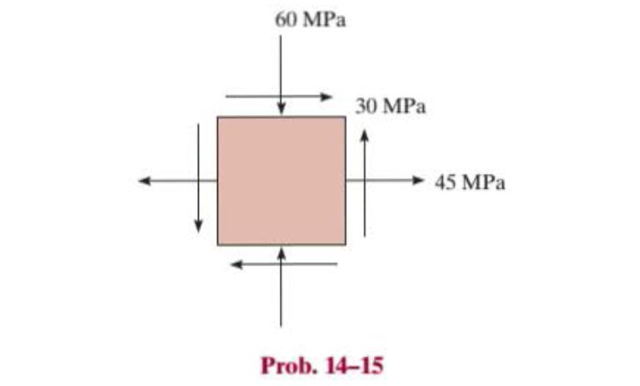
Solve Prob. 14–15 using Mohr’s circle.
14–15. The state of stress at a point is shown on the element. Determine (a) the principal stresses and (b) the maximum in-plane shear stress and average normal stress at the point. Specify the orientation of the element in each case.
Expert Solution & Answer
Want to see the full answer?
Check out a sample textbook solution
Students have asked these similar questions
Determine (a) the principal stresses and (b) the maximum in-plane shear stress and average normal stress at the point. Specify the orientation of the element in each case.
Determine the average normal stress at points A, B, and C. The diameter of each segment is indicated in the figure.
Determine the average normal stress developed at points A, B, and C. The diameter of each segment is indicated in the figure.
Chapter 14 Solutions
Statics and Mechanics of Materials (5th Edition)
Ch. 14.3 - In each ease, the state of stress x, y, xy...Ch. 14.3 - Given the state of stress shown on the element,...Ch. 14.3 - Determine the normal stress and shear stress...Ch. 14.3 - Prob. 2FPCh. 14.3 - Determine the equivalent state of stress on an...Ch. 14.3 - Prob. 4FPCh. 14.3 - The beam is subjected to the load at its end....Ch. 14.3 - Prob. 6FPCh. 14.3 - Prove that the sum of the normal stresses x+y=x+y...Ch. 14.3 - Determine the stress components acting on the...
Ch. 14.3 - Determine the stress components acting on the...Ch. 14.3 - Determine the normal stress and shear stress...Ch. 14.3 - Determine the normal stress and shear stress...Ch. 14.3 - Prob. 6PCh. 14.3 - Prob. 7PCh. 14.3 - Determine the stress components acting on the...Ch. 14.3 - Determine the stress components acting on the...Ch. 14.3 - Determine the stress components acting on the...Ch. 14.3 - Determine the equivalent state of stress on an...Ch. 14.3 - Prob. 12PCh. 14.3 - Determine the stress components acting on the...Ch. 14.3 - Determine (a) the principal stresses and (b) the...Ch. 14.3 - Prob. 15PCh. 14.3 - Prob. 16PCh. 14.3 - Prob. 17PCh. 14.3 - Prob. 18PCh. 14.3 - Prob. 19PCh. 14.3 - Prob. 20PCh. 14.3 - Prob. 21PCh. 14.3 - The state of stress at a point in a member is...Ch. 14.3 - The wood beam is subjected to a load of 12 kN. If...Ch. 14.3 - Prob. 24PCh. 14.3 - The internal loadings at a section of the beam are...Ch. 14.3 - The internal loadings at a section of the beam are...Ch. 14.3 - Prob. 27PCh. 14.3 - Prob. 28PCh. 14.3 - The beam has a rectangular cross section and is...Ch. 14.3 - A paper tube is formed by rolling a cardboard...Ch. 14.3 - Prob. 31PCh. 14.3 - The 2-in.-diameter drive shaft AB on the...Ch. 14.3 - Determine the principal stresses in the...Ch. 14.3 - The internal loadings at a cross section through...Ch. 14.3 - The internal loadings at a cross section through...Ch. 14.3 - Prob. 36PCh. 14.3 - The steel pipe has an inner diameter of 2.75 in....Ch. 14.3 - Prob. 38PCh. 14.3 - The wide-flange beam is subjected to the 50-kN...Ch. 14.3 - Prob. 40PCh. 14.3 - The box beam is subjected to the 26-kN force that...Ch. 14.3 - The box beam is subjected to the 26-kN force that...Ch. 14.4 - Use Mohrs circle to determine the normal stress...Ch. 14.4 - Prob. 8FPCh. 14.4 - Prob. 9FPCh. 14.4 - Prob. 10FPCh. 14.4 - Prob. 11FPCh. 14.4 - Prob. 12FPCh. 14.4 - Solve Prob. 142 using Mohrs circle. 14-2.Determine...Ch. 14.4 - Solve Prob. 143 using Mohrs circle. 143.Determine...Ch. 14.4 - Determine the stress components acting on the...Ch. 14.4 - Solve Prob. 1410 using Mohrs circle. 149.Determine...Ch. 14.4 - Solve Prob. 1415 using Mohrs circle. 1415.The...Ch. 14.4 - Solve Prob. 1416 using Mohrs circle....Ch. 14.4 - Prob. 49PCh. 14.4 - Determine (a) the principal stresses and (b) the...Ch. 14.4 - Determine (a) the principal stresses and (b) the...Ch. 14.4 - Determine the equivalent state of stress if an...Ch. 14.4 - Draw Mohrs circle that describes each of the...Ch. 14.4 - Draw Mohrs circle that describes each of the...Ch. 14.4 - Determine (a) the principal stresses and (b) the...Ch. 14.4 - Determine (a) the principal stress and (b) the...Ch. 14.4 - Determine (a) the principal stresses and (b) the...Ch. 14.4 - Determine (a) the principal stresses and (b) the...Ch. 14.4 - Determine (a) the principal stresses and (b) the...Ch. 14.4 - Prob. 60PCh. 14.4 - The grains of wood in the board make an angle of...Ch. 14.4 - The post is fixed supported at its base and a...Ch. 14.4 - Determine the principal stresses, the maximum...Ch. 14.4 - The thin-walled pipe has an inner diameter of 0.5...Ch. 14.4 - The frame supports the triangular distributed load...Ch. 14.4 - The frame supports the triangular distributed load...Ch. 14.4 - Prob. 67PCh. 14.4 - The pedal crank for a bicycle has the cross...Ch. 14.4 - A spherical pressure vessel has an inner radius of...Ch. 14.4 - The cylindrical pressure vessel has an inner...Ch. 14.4 - Prob. 71PCh. 14.4 - Determine the principal stress at point D, which...Ch. 14.4 - If the box wrench is subjected to the 50 lb force,...Ch. 14.4 - If the box wrench is subjected to the 50-lb force,...Ch. 14.4 - Prob. 75PCh. 14.5 - Draw the three Mohrs circles that describe each of...Ch. 14.5 - Draw the three Mohrs circles that describe the...Ch. 14.5 - Draw the three Mohrs circles that describe the...Ch. 14.5 - Determine the principal stresses and the absolute...Ch. 14.5 - Prob. 80PCh. 14.5 - Prob. 81PCh. 14.5 - Prob. 82PCh. 14.8 - Prove that the sum of the normal strains in...Ch. 14.8 - The state of strain at the point on the arm has...Ch. 14.8 - The state of strain at the point on the pin leaf...Ch. 14.8 - The state of strain at the point on the pin leaf...Ch. 14.8 - Prob. 88PCh. 14.8 - The state of strain at a point on the bracket has...Ch. 14.8 - Prob. 90PCh. 14.8 - Prob. 91PCh. 14.8 - Prob. 92PCh. 14.8 - Prob. 93PCh. 14.8 - Prob. 94PCh. 14.8 - Prob. 95PCh. 14.8 - Prob. 96PCh. 14.8 - Prob. 97PCh. 14.8 - The state of strain on the element has components...Ch. 14.8 - Solve Prob. 1486 using Mohrs circle. 1486.The...Ch. 14.8 - Solve Prob. 1487 using Mohrs circle. 1486.The...Ch. 14.8 - Solve Prob. 1488 using Mohrs circle. 1488.The...Ch. 14.8 - Solve Prob. 1491 using Mohrs circle. 1491.The...Ch. 14.8 - Solve Prob. 1490 using Mohrs circle. 1489.The...Ch. 14.11 - The strain at point A on the bracket has...Ch. 14.11 - The strain at point A on a beam has components...Ch. 14.11 - The strain at point A on the pressure-vessel wall...Ch. 14.11 - The 45 strain rosette is mounted on the surface of...Ch. 14.11 - Prob. 109PCh. 14.11 - Use Hookes law, Eq. 1432, to develop the strain...Ch. 14.11 - Prob. 111PCh. 14.11 - A rod has a radius of 10 mm. If it is subjected to...Ch. 14.11 - The polyvinyl chloride bar is subjected to an...Ch. 14.11 - The polyvinyl chloride bar is subjected to an...Ch. 14.11 - The spherical pressure vessel has an inner...Ch. 14.11 - Determine the bulk modulus for each of the...Ch. 14.11 - The strain gage is placed on the surface of the...Ch. 14.11 - The principal strains at a point on the aluminum...Ch. 14.11 - Prob. 119PCh. 14.11 - Prob. 120PCh. 14.11 - The cube of aluminum is subjected to the three...Ch. 14.11 - The principal strains at a point on the aluminum...Ch. 14.11 - A uniform edge load of 500 lb/in. and 350 lb/in....Ch. 14.11 - Prob. 124PCh. 14 - The steel pipe has an inner diameter of 2.75 in....Ch. 14 - Prob. 2RPCh. 14 - Prob. 3RPCh. 14 - The crane is used to support the 350-lb load....Ch. 14 - In the case of plane stress, where the in-plane...Ch. 14 - The plate is made of material having a modulus of...Ch. 14 - If the material is graphite for which Eg = 800 ksi...Ch. 14 - A single strain gage, placed in the vertical plane...Ch. 14 - The 60 strain rosette is mounted on a beam. The...
Knowledge Booster


Learn more about
Need a deep-dive on the concept behind this application? Look no further. Learn more about this topic, mechanical-engineering and related others by exploring similar questions and additional content below.Similar questions
- Determine (a) the principal stresses and (b) the maximum in-plane shear stress and average normal stress. Specify the orientation of the element in each case.arrow_forward6kN and 1.0KNM loads are applied to the top of the 62-mm-diameter cast-iron as shown. Determine the principal stresses (max and min normal stresses), principal planes (orientation of plane for max-min normal stresses) and max shear stress by using Mohr's circle. Hint: Use given coordinate system. So, H is on x-z plane and K is on y- z plane 1.0 kN.m 6 kN X 220 mmarrow_forward4 ksi The state of plane stress at a point is shown on the element. (a) Draw Mohr's circle neatly to scale, and use it to complete part (b). (b) Determine the state of stress on an element rotated 35° counterclock- 20 ksi wise from the given element. Sketch the state of stress on the rotated element element. 9 ksi -20 -10 o (ksi) -30 -20 -10 10 20 30 10 20 T (ksi)arrow_forward
- The beveled gear is subjected to the loads shown.Determine the stress components acting on the shaftat point B, and draw the results on a stress elementat this point. The shaft has a diameter of 1 in. and isfixed to the wall at C. A = 0.7854 in2 J = 0.098175 in4 I = 0.049087 in4 (QB)z = 0 (QB)x = 0.0833 in3arrow_forwardThe state of stress at a point is shown on the element. Determine (a) the principal stresses and (b) the maximum in-plane shear stress and average normal stress at the point. Specify the orientation of the element in each case.arrow_forwardThe book is subjected to the force of 60 lb Determine the state of stress at point A at section a-a. The cross section is circular and has a diameter of 0.5 in. Use the curved-beam formula to compute the bending stress (Figure 1) Figure 1.5 in. 13 45° B 1 of 1 > ▾ Part A Determine the normal stress. Express your answer using three significant figures and include the appropriate units. Enter negative value in the case of compression and positive value in the case of tension. g= Value Submit Part B ← A psi Previous Answers Request Answer X Incorrect; Try Again; 4 attempts remaining ✓ Correct < Return to Assignment Ċ 129 ? Determine the shear stress Express your answer using three significant figures and include the appropriate units. T= 0 psi Previous Answers Provide Feedbackarrow_forward
- Consider the given state of stress. Given: X = 7 ksi and Y = 35 ksi. Determine the normal stress using Mohr's circle.arrow_forwardThe 20 mm diameter rod is subjected to the loads shown. (a) Determine the state of stress at point A and show the results on a differential element located at this point. (b) Using Mohr's circle, determine the maximum normal stress and the maximum in-plane shearing stress at point A and show the associated stress states on appropriately oriented elements, for each case. 75 mm 375 N B 200 mm 450 Narrow_forwardThe solid cylinder having a radius r is placed in a sealed container and subjected to a pressure p. Determine the stress components acting at point A located on the center line of the cylinder. Draw Mohr's circles for the element at this point. Aarrow_forward
- 5. Two forces act on the solid circular rod (r=.005 m) as shown. Using Mohr's circle, determine the principal stresses and the absolute maximum in plane shear stress at point A. 100 mm 150 mm 500 N V 300 N -•64- o (M Pa) 6.l12 -64 T (MPa) Taug = 6.l12 R=Vo2037+ 3.0562 =3.062 M Pa O; = R+ Jarg; 0,=60119MPQ t 3.0 0056 M Pa T,= Oava - R; 2 0068 MPaa Therefore Tabs =R= 3.062MPaa maxarrow_forward*9–12. Determine the equivalent state of stress on an element if it is oriented 50° counterclockwise from the element shown. Use the stress-transformation equations. 10 ksi 16 ksi Prob. 9–12arrow_forwardDetermine the principal stresses and the absolute maximum shear stress.arrow_forward
arrow_back_ios
SEE MORE QUESTIONS
arrow_forward_ios
Recommended textbooks for you
 Elements Of ElectromagneticsMechanical EngineeringISBN:9780190698614Author:Sadiku, Matthew N. O.Publisher:Oxford University Press
 Mechanics of Materials (10th Edition)Mechanical EngineeringISBN:9780134319650Author:Russell C. HibbelerPublisher:PEARSON
 Thermodynamics: An Engineering ApproachMechanical EngineeringISBN:9781259822674Author:Yunus A. Cengel Dr., Michael A. BolesPublisher:McGraw-Hill Education
 Control Systems EngineeringMechanical EngineeringISBN:9781118170519Author:Norman S. NisePublisher:WILEY
 Mechanics of Materials (MindTap Course List)Mechanical EngineeringISBN:9781337093347Author:Barry J. Goodno, James M. GerePublisher:Cengage Learning
 Engineering Mechanics: StaticsMechanical EngineeringISBN:9781118807330Author:James L. Meriam, L. G. Kraige, J. N. BoltonPublisher:WILEY
Elements Of Electromagnetics
Mechanical Engineering
ISBN:9780190698614
Author:Sadiku, Matthew N. O.
Publisher:Oxford University Press
Mechanics of Materials (10th Edition)
Mechanical Engineering
ISBN:9780134319650
Author:Russell C. Hibbeler
Publisher:PEARSON
Thermodynamics: An Engineering Approach
Mechanical Engineering
ISBN:9781259822674
Author:Yunus A. Cengel Dr., Michael A. Boles
Publisher:McGraw-Hill Education
Control Systems Engineering
Mechanical Engineering
ISBN:9781118170519
Author:Norman S. Nise
Publisher:WILEY
Mechanics of Materials (MindTap Course List)
Mechanical Engineering
ISBN:9781337093347
Author:Barry J. Goodno, James M. Gere
Publisher:Cengage Learning
Engineering Mechanics: Statics
Mechanical Engineering
ISBN:9781118807330
Author:James L. Meriam, L. G. Kraige, J. N. Bolton
Publisher:WILEY
Understanding Torsion; Author: The Efficient Engineer;https://www.youtube.com/watch?v=1YTKedLQOa0;License: Standard YouTube License, CC-BY