
Mechanics of Materials
11th Edition
ISBN: 9780137605460
Author: Russell C. Hibbeler
Publisher: Pearson Education (US)
expand_more
expand_more
format_list_bulleted
Videos
Textbook Question
Chapter 1.5, Problem 49P
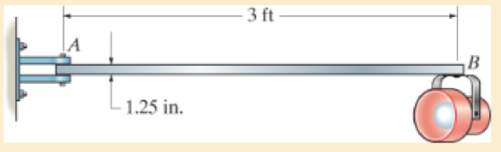
The railcar docklight is supported by the
Expert Solution & Answer
Want to see the full answer?
Check out a sample textbook solution
Students have asked these similar questions
The railcar docklight is supported by the 1/8-in.-diameter pin at A. If the lamp weighs 4.1 lb, and the extension arm AB has a weight of 0.6 lb/ft.
3 ft
-1.25 in
Part A
Determine the average shear stress in the pin needed to support the lamp. Hint:The shear force in the pin is caused by the couple moment required for equilibrium at A.
Express your answer to three significant figures and include appropriate units.
Value
Units
The lever is held to the fixed shaft using the pin AB. If the couple is applied to the lever, determine the shear force in the pin between the pin and the lever.
The bar AB is supported by a frictionless inclined surface at A and a 7/8-in.-diameter pin at B that is in double shear. Determine the shear stress in the pin when the vertical 2000-lb force is applied. Neglect the weight of the bar.
Chapter 1 Solutions
Mechanics of Materials
Ch. 1.2 - Determine the resultant internal normal force,...Ch. 1.2 - Determine the resultant internal normal force,...Ch. 1.2 - Determine the resultant internal normal force,...Ch. 1.2 - Determine the resultant internal normal force,...Ch. 1.2 - Determine the resultant internal normal force,...Ch. 1.2 - Determine the resultant internal normal force,...Ch. 1.2 - The shaft is supported by a smooth thrust bearing...Ch. 1.2 - Determine the resultant internal normal and shear...Ch. 1.2 - Determine the resultant internal torque acting on...Ch. 1.2 - Determine the resultant internal loadings in the...
Ch. 1.2 - The shaft is supported by a smooth thrust bearing...Ch. 1.2 - Determine the resultant internal loading on the...Ch. 1.2 - Determine the resultant internal loading on the...Ch. 1.2 - The 800-lb load is being hoisted at a constant...Ch. 1.2 - Determine resultant internal loadings acting on...Ch. 1.2 - Determine the resultant internal normal force...Ch. 1.2 - Determine the resultant internal loadings on the...Ch. 1.2 - Determine the resultant internal loadings on the...Ch. 1.2 - The blade of the hacksaw is subjected to a...Ch. 1.2 - The blade of the hacksaw is subjected to a...Ch. 1.2 - Determine the resultant internal loadings on the...Ch. 1.2 - Determine the resultant internal loadings on the...Ch. 1.2 - The sky hook is used to support the cable of a...Ch. 1.2 - Determine the resultant internal torque acting on...Ch. 1.2 - Determine the resultant internal loadings acting...Ch. 1.2 - Determine the resultant internal loadings on the...Ch. 1.2 - Determine the resultant internal loadings on the...Ch. 1.2 - The metal stud punch is subjected to a force of...Ch. 1.2 - The metal stud punch is subjected to a force of...Ch. 1.2 - Determine the resultant internal loadings acting...Ch. 1.2 - A force of 80 N is supported by the bracket....Ch. 1.2 - The curved rod has a radius r and is fixed to the...Ch. 1.2 - The pipe assembly is subjected to a force of 600 N...Ch. 1.2 - If the drill bit jams when the handle of the hand...Ch. 1.2 - The curved rod AD of radius r has a weight per...Ch. 1.2 - A differential element taken from a curved bar is...Ch. 1.5 - The uniform beam is supported by two rods AB and...Ch. 1.5 - Determine the average normal stress on the cross...Ch. 1.5 - Determine the average normal stress on the cross...Ch. 1.5 - If the 600-kN force acts through the centroid of...Ch. 1.5 - Determine the average normal stress at points A,...Ch. 1.5 - Determine the average normal stress in rod AB if...Ch. 1.5 - A 175-lb woman stands on a vinyl floor wearing...Ch. 1.5 - Determine the largest intensity w of the uniform...Ch. 1.5 - The specimen failed in a tension test at an angle...Ch. 1.5 - The built-up shaft consists of a pipe AB and solid...Ch. 1.5 - If the material fails when the average normal...Ch. 1.5 - If the block is subjected to a centrally applied...Ch. 1.5 - The plate has a width of 0.5 m. If the stress...Ch. 1.5 - The member is subjected to a tensile force of 200...Ch. 1.5 - The boom has a uniform weight of 600 lb and is...Ch. 1.5 - Determine the average normal stress in each of the...Ch. 1.5 - If the average normal stress in each of the...Ch. 1.5 - Determine the maximum average shear stress in pin...Ch. 1.5 - The 150-kg bucket is suspended from end E of the...Ch. 1.5 - The 150-kg bucket is suspended from end E of the...Ch. 1.5 - If the pedestal is subjected to a compressive...Ch. 1.5 - The beam is supported by two rods AB and CD that...Ch. 1.5 - The beam is supported by two rods AB and CD that...Ch. 1.5 - The beam is supported by a pin at B and a short...Ch. 1.5 - The railcar docklight is supported by the...Ch. 1.5 - The plastic block is subjected to an axial...Ch. 1.5 - During a tension test, the wooden specimen is...Ch. 1.5 - The bar has a cross-sectional area of 400(106) m2....Ch. 1.5 - The bar has a cross-sectional area of 400(106) m2....Ch. 1.5 - Prob. 54PCh. 1.5 - The 2-Mg concrete pipe has a center of mass at...Ch. 1.5 - The 2-Mg concrete pipe has a center of mass at...Ch. 1.5 - The pier is made of material having a specific...Ch. 1.5 - Prob. 58PCh. 1.5 - The uniform bar, having a cross-sectional area of...Ch. 1.5 - Prob. 60PCh. 1.5 - Prob. 61PCh. 1.5 - The triangular blocks are glued along each side of...Ch. 1.5 - The triangular blocks are glued along each side of...Ch. 1.5 - Prob. 64PCh. 1.5 - Determine the maximum magnitude P of the load the...Ch. 1.5 - Prob. 66PCh. 1.5 - Prob. 67PCh. 1.7 - Rods AC and BC are used to suspend the 200-kg...Ch. 1.7 - If it is subjected to double shear, determine the...Ch. 1.7 - Determine the maximum average shear stress...Ch. 1.7 - If each of the three nails has a diameter of 4 mm...Ch. 1.7 - The strut is glued to the horizontal member at...Ch. 1.7 - Determine the maximum average shear stress...Ch. 1.7 - If the eyebolt is made of a material having a...Ch. 1.7 - If the bar assembly is made of a material having a...Ch. 1.7 - Determine the maximum force P that can be applied...Ch. 1.7 - The pin is made of a material having a failure...Ch. 1.7 - If the bolt head and the supporting bracket are...Ch. 1.7 - Six nails are used to hold the hanger at A against...Ch. 1.7 - If A and B are both made of wood and are 38 in....Ch. 1.7 - Prob. 70PCh. 1.7 - The connection is made using a bolt and nut and...Ch. 1.7 - Determine the required cross-sectional area of...Ch. 1.7 - Prob. 73PCh. 1.7 - The spring mechanism is used as a shock absorber...Ch. 1.7 - Prob. 75PCh. 1.7 - The hangers support the joist in such a way that...Ch. 1.7 - Prob. 77PCh. 1.7 - Prob. 78PCh. 1.7 - The two aluminum rods AB and BC have diameters of...Ch. 1.7 - The cotter is used to hold the two rods together....Ch. 1.7 - Prob. 81PCh. 1.7 - The 60mm60mm oak post is supported on the pine...Ch. 1.7 - Prob. 83PCh. 1.7 - Prob. 84PCh. 1.7 - The assembly consists of three disks A, B, and C...Ch. 1.7 - Prob. 86PCh. 1.7 - Prob. 87PCh. 1.7 - Prob. 88PCh. 1.7 - Prob. 89PCh. 1.7 - Prob. 90PCh. 1.7 - Prob. 91PCh. 1.7 - Prob. 92PCh. 1.7 - Prob. 93PCh. 1.7 - The aluminum bracket A is used to support the...Ch. 1.7 - If the allowable tensile stress for the bar is...Ch. 1.7 - The bar is connected to the support using a pin...Ch. 1 - The beam AB is pin supported at A and supported by...Ch. 1 - The long bolt passes through the 30-mm-thick...Ch. 1 - Determine the required thickness of member BC to...Ch. 1 - The circular punch B exerts a force of 2 kN on the...Ch. 1 - Determine the average punching shear stress the...Ch. 1 - The 150 mm by 150 mm block of aluminum supports a...Ch. 1 - The yoke-and-rod connection is subjected to a...Ch. 1 - The cable has a specific weight (weight/volume)...
Knowledge Booster


Learn more about
Need a deep-dive on the concept behind this application? Look no further. Learn more about this topic, mechanical-engineering and related others by exploring similar questions and additional content below.Similar questions
- Railroad ties must be designed to resist large shear loadings. If the tie is subjected to the 34-kip rail loadings and an assumed uniformly distributed ground reaction, determine the intensity w for equilibrium, and calculate themaximum shear stress in the tie at section a–a, which is located just to the left of the rail.arrow_forwardThe man has a mass of 100 kg and center of mass at G. If he holds himself in the position shown, determine the maximum tensile and compressive stress developed in the curved bar at section a–a. He is supported uniformly by twobars, each having a diameter of 25 mm. Assume the floor is smooth. Use the curved-beam formula to calculate the bending stress.arrow_forwardIf the allowable shear stress for each of the 10-mm-diameter steel pins at A, B, and C is allow = 90 MPa, and the allowable normal stress for the 13-mm-diameter rod is allow = 150 MPa, determine the largest intensity w of the uniform distributed load that can be suspended from the beam.arrow_forward
- The bracket is held to the wall using three A-36 steel bolts at B, C, and D. Each bolt has a diameter of 0.5 in. and an unstretched length of 2 in. If a force of 800 lb is placed on the bracket as shown,determine the force developed in each bolt. For the calculation, assume that the bolts carry no shear; rather, the vertical force of 800 lb is supported by the toe at A. Also, assume that the wall and bracket are rigid. A greatly exaggerated deformation of the bolts is shown.arrow_forwardThe bracket is held to the wall using three A-36 steel bolts at B, C, and D. Each bolt has a diameter of 0.5 in. and an unstretched length of 2 in. If a force of 800 lb is placed on the bracket as shown, determine the force developed in each bolt. For the calculation, assume that the bolts carry no shear; rather, the vertical force of 800 lb is supported by the toe at A. Also, assume that the wall and bracket are rigid. A greatly exaggerated deformation of the bolts is shown.arrow_forwardDetermine the normal stress and shear stress acting on the inclined plane AB. Solve the problem using the method of equilibrium described in Sec.arrow_forward
- Determine the magnitude of the pin force at A. Assume W = 900 Ib, a = 5.8 ft, b = 3.9 ft, r = 9 in. B W Answer: A = i Ibarrow_forwardThe circular punch B exerts a force of 2 kN on the top of the plate A. Determine the average shear stress in the plate due to this loading.arrow_forwardThe assembly consists of two sections of galvanized steel pipe connected together using a reducing coupling at B. The smaller pipe has an outer diameter of 0.75 in. and an inner diameter of 0.68 in., whereas the larger pipe has an outer diameter of 1 in. and an inner diameter of 0.86 in. If the pipe istightly secured to the wall at C, determine the maximum shear stress in each section of the pipe when the couple is applied to the handles of the wrench.arrow_forward
- Determine the magnitude of the pin force at A. Assume W = 830 lb, a = 5.5 ft, b = 4.0 ft, r = 8 in. r W с Answer: A = i a B a A D lb barrow_forwardDetermine the magnitude of the pin force at A. Assume W = 670 lb, a = 5.2 ft, b = 3.5 ft, r = 7 in. r W C Answer: A = i a B A D lb barrow_forwardThe rigid bar AB and CD are supported by pins at A and D. the vertical rods are made of aluminum and bronze. Determine the vertical displacement of the point where the force P= 10 kips is applied. Neglect the weight of the members.arrow_forward
arrow_back_ios
SEE MORE QUESTIONS
arrow_forward_ios
Recommended textbooks for you
 Elements Of ElectromagneticsMechanical EngineeringISBN:9780190698614Author:Sadiku, Matthew N. O.Publisher:Oxford University Press
 Mechanics of Materials (10th Edition)Mechanical EngineeringISBN:9780134319650Author:Russell C. HibbelerPublisher:PEARSON
 Thermodynamics: An Engineering ApproachMechanical EngineeringISBN:9781259822674Author:Yunus A. Cengel Dr., Michael A. BolesPublisher:McGraw-Hill Education
 Control Systems EngineeringMechanical EngineeringISBN:9781118170519Author:Norman S. NisePublisher:WILEY
 Mechanics of Materials (MindTap Course List)Mechanical EngineeringISBN:9781337093347Author:Barry J. Goodno, James M. GerePublisher:Cengage Learning
 Engineering Mechanics: StaticsMechanical EngineeringISBN:9781118807330Author:James L. Meriam, L. G. Kraige, J. N. BoltonPublisher:WILEY
Elements Of Electromagnetics
Mechanical Engineering
ISBN:9780190698614
Author:Sadiku, Matthew N. O.
Publisher:Oxford University Press
Mechanics of Materials (10th Edition)
Mechanical Engineering
ISBN:9780134319650
Author:Russell C. Hibbeler
Publisher:PEARSON
Thermodynamics: An Engineering Approach
Mechanical Engineering
ISBN:9781259822674
Author:Yunus A. Cengel Dr., Michael A. Boles
Publisher:McGraw-Hill Education
Control Systems Engineering
Mechanical Engineering
ISBN:9781118170519
Author:Norman S. Nise
Publisher:WILEY
Mechanics of Materials (MindTap Course List)
Mechanical Engineering
ISBN:9781337093347
Author:Barry J. Goodno, James M. Gere
Publisher:Cengage Learning
Engineering Mechanics: Statics
Mechanical Engineering
ISBN:9781118807330
Author:James L. Meriam, L. G. Kraige, J. N. Bolton
Publisher:WILEY
Everything About TRANSVERSE SHEAR in 10 Minutes!! - Mechanics of Materials; Author: Less Boring Lectures;https://www.youtube.com/watch?v=4x0E9yvzfCM;License: Standard Youtube License