
Fundamentals of Geotechnical Engineering (MindTap Course List)
5th Edition
ISBN: 9781305635180
Author: Braja M. Das, Nagaratnam Sivakugan
Publisher: Cengage Learning
expand_more
expand_more
format_list_bulleted
Concept explainers
Videos
Textbook Question
Chapter 18, Problem 18.20P
Figure 18.26a shows a pile. Let L = 20 m, D = 450 mm. Hf = 4m, γf = 17.5 kN/m3, ϕ′fill = 25°. Determine the total downward drag force on the pile. Assume that the fill is located above the water table and that δ′ = 0.5 ϕ′fill.
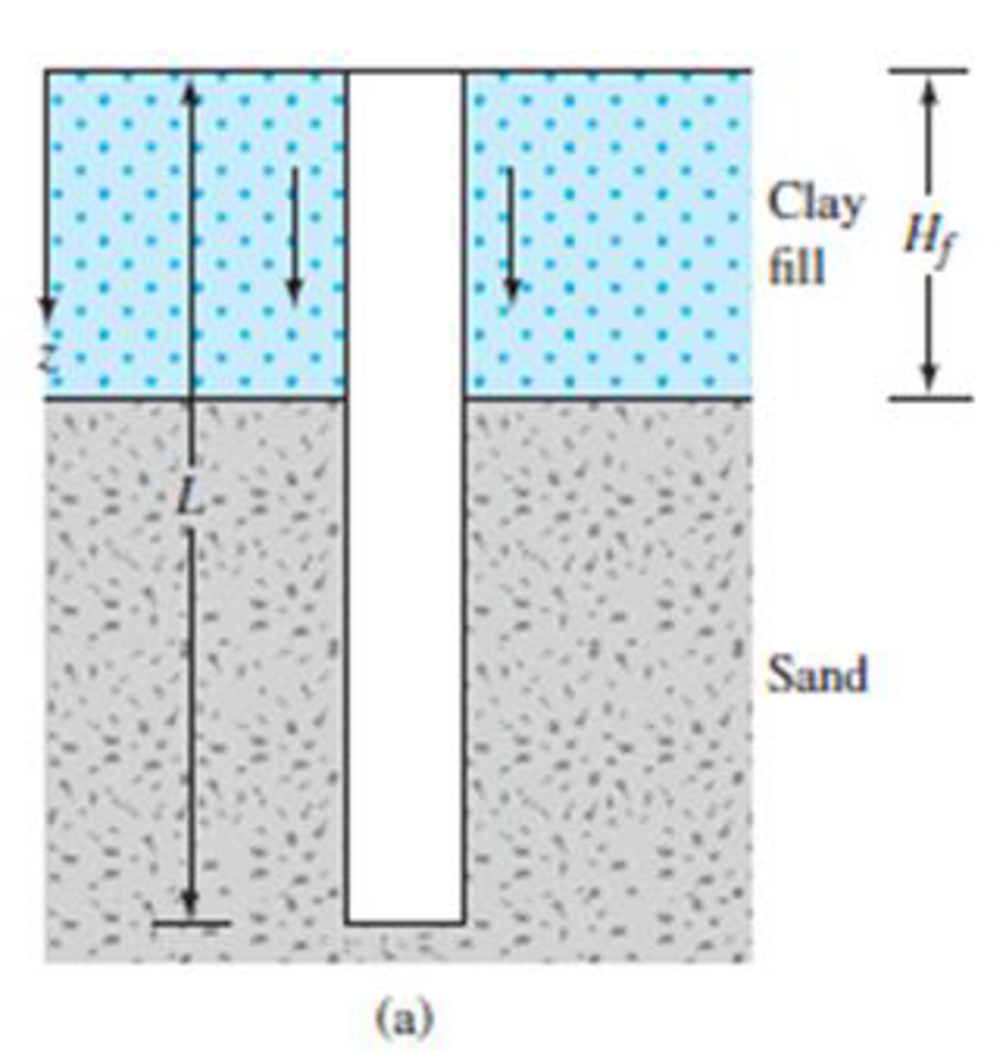
FIG. 18.26 Negative skin friction
Expert Solution & Answer
Want to see the full answer?
Check out a sample textbook solution
Students have asked these similar questions
Refer to the pile shown in Figure P 9.1. Estimate the side resistance Qs bya. Using Eqs. (9.40) through (9.42). Use K = 1.5 and ẟ' = 0.6 Φ'b. Coyle and Castello’s method [Eq. (9.44)]
11.22 A concrete pile measuring 0.406 m X 0.406 m in cross section is 18.3 m long. It is
fully embedded in a layer of sand. The following is an approximation of the me-
chanical cone penetration resistance (q.) and the friction ratio (F) for the sand
layer. Estimate the allowable bearing capacity of the pile. Use FS = 4.
Depth below ground surface (m)
9. (kN/m²)
F, (%)
0-6.1
2803
2.3
6.1-13.7
3747
2.7
13.7-19.8
8055
2.8
A 450 mm x 450 mm concrete pile 20.0 m long is driven into sand deposits with y = 17 kN/m³ and
= 30°. Find the ultimate load i.e. point load Qp by Meyerhoff's method and Janbu method.
Meyerhoff's N = 55, Atmospheric pressure = 100 kN/m², Janbu's N = 18.4
Chapter 18 Solutions
Fundamentals of Geotechnical Engineering (MindTap Course List)
Ch. 18 - State whether the following are true or false. a....Ch. 18 - A 1500 kN load was applied on two 20 m long and...Ch. 18 - A 500 mm diameter and 20 m long concrete pile is...Ch. 18 - A 400-mm diameter and 15 m long concrete pile is...Ch. 18 - A 400 mm 400 mm square precast concrete pile of...Ch. 18 - Prob. 18.6PCh. 18 - Prob. 18.7PCh. 18 - Prob. 18.8PCh. 18 - Determine the maximum load that can be allowed on...Ch. 18 - Prob. 18.10P
Ch. 18 - Redo Problem 18.10 using the method for...Ch. 18 - Determine the maximum load that can be allowed on...Ch. 18 - Prob. 18.13PCh. 18 - A steel pile (H-section; HP 360 1.491; see Table...Ch. 18 - A concrete pile is 18 m long and has a cross...Ch. 18 - Prob. 18.16PCh. 18 - Prob. 18.17PCh. 18 - Prob. 18.18PCh. 18 - Prob. 18.19PCh. 18 - Figure 18.26a shows a pile. Let L = 20 m, D = 450...Ch. 18 - Refer to Figure 18.26b. Let L = 15.24 m, fill =...Ch. 18 - Prob. 18.22PCh. 18 - Figure 18.39 shows a 3 5 pile group consisting of...Ch. 18 - The section of a 4 4 group pile in a layered...Ch. 18 - Prob. 18.25PCh. 18 - Prob. 18.26CTP
Knowledge Booster


Learn more about
Need a deep-dive on the concept behind this application? Look no further. Learn more about this topic, civil-engineering and related others by exploring similar questions and additional content below.Similar questions
- 4. For the cantilever sheet pile wall, compute the depth of Embedment of sheet pile by the approximate method. T 3 m 3 m D 3 Y = 1.9 t/m³ = 30° Y' = 1.0 t/m³ = 30°arrow_forwardDetermine the diameter of 70 ft long pile driven in the medium dense sand (Shown in Figure). Design load is 185Kips and factor of safety can be assumed to be 2.5. Frictional coefficient is 0.45 Sand y = 115lb/ft3 Ø = 28° K = 0.80 30 %3D Sand 128lb/ft %3! Ysat Ø= 30° K = 0.85 33°C 70arrow_forward12.2 A 20 m long concrete pile is shown in Figure P12.2. Estimate the ultimate point load Q, by a. Meyerhof's method b. Vesic's method c. Coyle and Castello's method Use m = 600 in Eq. (12.28). Concrete pile 460 mm x 460 mm 20 m Loose sand +1-30° y- 18.6 kN/m³ FIGURE P 12.2 Dense sand 2-42° y 18.5 kN/m³arrow_forward
- A concrete pile 20 m long having a cross section of 0.46 m × 0.46 m is fully embedded in a saturated clay layer. For the clay, given: Yat = 18 kN/m², = 0, and Cu = 80 kN/m?. Determine the allowable load that the pile can carry (FS = 3). Use %3D the A method to estimate the skin resistance.arrow_forwardConsider a drilled, rough concrete pile with diameter B = 1m and length D = 10m embedded in a site underlain by a 5m thick layer of sand with fiction angle = 41 degrees and Ko = 0.5 that lies over an 8m thick layer of clay with fiction angle = 36 degrees, Ko = 0.38, and Su = 70 kPa. a. Determine the long term end bearing capacity of the pile. b. Determine the long term capacity of the pile.arrow_forward3. Determine the maximum load that can be allowed on a 45cm x 45cm diameter bored pile shown in Figure-1 allowing a factor of safety of 3. Take SPT value at the bottom of pile 40. Sand y = 17.0 kN/m o' = 31° 8 m Sand 10 m Ysat = 19.0 kN/m³ O' = 33° Figure - 1arrow_forward
- A 20-m-long concrete pile is shown in Figure P9.1. Estimate the ultimate point load Q, by a. Meyerhof's method b. Vesic's method c. Coyle and Castello's method Use m = 600 in Eq. (9.26). 9.1 Concrete pile 460 mm x 460 mm Loose sand di = 30° y = 18.6 kN/m3 20 m Dense sand d'2 = 42° y = 18.5 kN/m3 Figure P9.1arrow_forwardQ.7 (a) A 500 mm diameter bored concrete pile is to be formed in the soil profile as shown in figure. The ground conditions are as follows: Granular soil: Dense gravel: Glacial clay: Depth (m) Adhesion factor, cat 7.0 m = 120 kPa c at 8.0 m 145 kPa cat 11.0 m 220 kPa 0 3 7 8 Y = 20 kN/m³ $' = 22.5° K₁ = 1.0 Y= 21 kN/m³ ' = 26.25° 11 K, = 2.0 Y = 20 kN/m³ α = 0.6 N = 9.0 Granular soil Dense gravel Glacial clay Determine the ultimate bearing capacity of the pile for: (a) Embedded length of 8 m (b) Embedded length of 11 marrow_forwardDraw a flow net for a single row of sheet piles driven into a permeable layer as showin Figure Q3 (b) below. Thus, determine the seepage loss per meter length of thesheet pile.H1 = 9.6 m D = 5 mH2 = 3.7 m D1 = 13 marrow_forward
- 9.27 The plan of a group pile is shown in Figure P9.27. Assume that the piles are embedded in a saturated homogeneous clay having a c = 90 kN/m². Given: diameter of piles (D) = 316 mm, center-to-center spacing of piles = 600 mm, and length of piles = 20 m. Find the allowable load-carrying capacity of the pile group. Use Table 9.10 and FS = 3. d Figure P9.27arrow_forwardA construction project of cantilever sheet pile penetrating saturated clay is designed to form a sheet pile wall along a riverbank as shown in Figure C. Determine: i. - ii. The theoretical and actual depth of penetration by using Dactual = 1.5D theory The maximum size of sheet pile section necessary by using all = 172.5 MN/m². Sand A y=16 kN/m³ c' = 0 2m Water table p=32 Sand Ysat 19.35 kN/m³ c' = 0 4'=32 Clay Vsat 19.35 kN/m³ c′ = 46.9 kN/m² 3m Figure C E B Riverbedarrow_forward12.2 A 20 m long concrete pile is shown in Figure P12.2. Estimate the ultimate point load Q, by a. Meyerhof's method b. Vesic's method c. Coyle and Castello's method Use m = 600 in Eq. (12.28). Concrete pile 460 mm X 460 mm Loose sand di = 30° y = 18.6 kN/m3 20 m F Dense sand $2 = 42° y = 18.5 kN/marrow_forward
arrow_back_ios
SEE MORE QUESTIONS
arrow_forward_ios
Recommended textbooks for you
 Fundamentals of Geotechnical Engineering (MindTap...Civil EngineeringISBN:9781305635180Author:Braja M. Das, Nagaratnam SivakuganPublisher:Cengage Learning
 Principles of Foundation Engineering (MindTap Cou...Civil EngineeringISBN:9781337705028Author:Braja M. Das, Nagaratnam SivakuganPublisher:Cengage Learning
 Principles of Foundation Engineering (MindTap Cou...Civil EngineeringISBN:9781305081550Author:Braja M. DasPublisher:Cengage Learning
Fundamentals of Geotechnical Engineering (MindTap...
Civil Engineering
ISBN:9781305635180
Author:Braja M. Das, Nagaratnam Sivakugan
Publisher:Cengage Learning
Principles of Foundation Engineering (MindTap Cou...
Civil Engineering
ISBN:9781337705028
Author:Braja M. Das, Nagaratnam Sivakugan
Publisher:Cengage Learning
Principles of Foundation Engineering (MindTap Cou...
Civil Engineering
ISBN:9781305081550
Author:Braja M. Das
Publisher:Cengage Learning
How to build angle braces; Author: Country Living With The Harnish's;https://www.youtube.com/watch?v=3cKselS6rxY;License: Standard Youtube License