
Fundamentals of Electric Circuits
6th Edition
ISBN: 9780078028229
Author: Charles K Alexander, Matthew Sadiku
Publisher: McGraw-Hill Education
expand_more
expand_more
format_list_bulleted
Concept explainers
Videos
Textbook Question
Chapter 2, Problem 6P
In the network graph shown in Fig. 2.70, determine the number of branches and nodes.
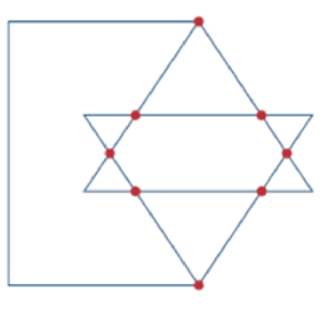
Figure 2.70
For Prob. 2.6.
Expert Solution & Answer
Want to see the full answer?
Check out a sample textbook solution
Students have asked these similar questions
Example: Find current i, and voltage in the circuit shown below using KCL
osi
3A
An independent voltage source is characterized by a terminal voltage which
Select one:
a. None of the above
b. is completely independent of the power dissipated by it.
c. is completely independent of the current through it.
d. is completely dependent on the current through it.
EX Find is, in the circuit below
15ma
2.7
Chapter 2 Solutions
Fundamentals of Electric Circuits
Ch. 2.2 - The essential component of a toaster is an...Ch. 2.2 - For the circuit shown in Fig. 2.9, calculate the...Ch. 2.2 - A resistor absorbs an instantaneous power of 30...Ch. 2.3 - How many branches and nodes does the circuit in...Ch. 2.4 - Find v1 and v2 in the circuit of Fig. 2.22. Figure...Ch. 2.4 - Find vx and vo in the circuit of Fig. 2.24. Figure...Ch. 2.4 - Find vo and io in the circuit of Fig. 2.26. Figure...Ch. 2.4 - Find the current and voltages in the circuit shown...Ch. 2.6 - By combining the resistors in Fig.2.36, find Req....Ch. 2.6 - Find Rab for the circuit in Fig.2.39. Figure 2.39...
Ch. 2.6 - Calculate Geq in the circuit of Fig.2.41. Figure...Ch. 2.6 - Find v1 and v2 in the circuit shown in Fig. 2.43....Ch. 2.7 - Transform the wye network in Fig. 2.51 to a delta...Ch. 2.7 - For the bridge network in Fig. 2.54, find Rab and...Ch. 2.8 - Refer to Fig. 2.55 and assume there are six light...Ch. 2.8 - Following the ammeter setup of Fig. 2.61. design...Ch. 2 - The reciprocal of resistance is: (a) voltage (b)...Ch. 2 - Prob. 2RQCh. 2 - Prob. 3RQCh. 2 - The maximum current that a 2W, 80 k resistor can...Ch. 2 - Prob. 5RQCh. 2 - The current I in the circuit of Fig. 2.63 is: (a)...Ch. 2 - The current I0 of Fig. 2.64 is: (a) 4 A (b) 2 A...Ch. 2 - In the circuit in Fig. 2.65, V is: (a) 30 V (b) 14...Ch. 2 - Which of the circuit in Fig. 2.66 will give you...Ch. 2 - In the circuit of Fig. 2.67, a decrease in R3...Ch. 2 - Design a problem, complete with a solution, to...Ch. 2 - Find the hot resistance of a light bulb rated 60...Ch. 2 - A bar of silicon is 4 cm long with a circular...Ch. 2 - (a) Calculate current i in Fig. 2.68 when the...Ch. 2 - For the network graph in Fig. 2.69. find the...Ch. 2 - In the network graph shown in Fig. 2.70, determine...Ch. 2 - Determine the number of branches and nodes in the...Ch. 2 - Design a problem, complete with a solution, to...Ch. 2 - Find i1, i2, and i3 in Fig. 2.73. Figure 2.73 For...Ch. 2 - Determine i1 and i2 in the circuit of Fig. 2.74....Ch. 2 - In the circuit of Fig. 2.75, calculate V1 and V2....Ch. 2 - In the circuit in Fig. 2.76, obtain v1, v2, and...Ch. 2 - For the circuit in Fig. 2.77, use KCL to find the...Ch. 2 - Given the circuit in Fig. 2.78, use KVL to find...Ch. 2 - Calculate v and ix in the circuit of Fig. 2.79....Ch. 2 - Determine Vo in the circuit in Fig. 2.80. Figure...Ch. 2 - Obtain v1 through v3 in the circuit of Fig. 2.81....Ch. 2 - Find I and V in the circuit of Fig. 2.82. Figure...Ch. 2 - From the circuit in Fig. 2.83, find I, the power...Ch. 2 - Determine io in the circuit of Fig. 2.84. Figure...Ch. 2 - Find Vx in the circuit of Fig. 2.85. Figure 2.85...Ch. 2 - Find Vo in the circuit in Fig. 2.86 and the power...Ch. 2 - In the circuit shown in Fig. 2.87, determine Vx...Ch. 2 - For the circuit in Fig. 2.88, find Vo/Vs in terms...Ch. 2 - For the network in Fig. 2.89, find the current,...Ch. 2 - For the circuit in Fig. 2.90, io = 3 A. Calculate...Ch. 2 - Calculate Io in the circuit of Fig. 2.91. Figure...Ch. 2 - Design a problem, using Fig. 2.92, to help other...Ch. 2 - All resistors (R) in Fig. 2.93 are 10 each. Find...Ch. 2 - For the circuit in Fig. 2.95, determine i1 to i5....Ch. 2 - Find i1 through i4 in the circuit in Fig. 2.96....Ch. 2 - Obtain v and i in the circuit of Fig. 2.97. Figure...Ch. 2 - Using series/parallel resistance combination, find...Ch. 2 - Calculate Vo and Io in the circuit of Fig. 2.99....Ch. 2 - Find i and Vo in the circuit of Fig. 2.100. Figure...Ch. 2 - Given the circuit in Fig. 2.101 and that the...Ch. 2 - Find Req and io in the circuit of Fig. 2.102....Ch. 2 - Evaluate Req looking into each set of terminals...Ch. 2 - For the ladder network in Fig. 2.104, find I and...Ch. 2 - If Req = 50 in the circuit of Fig. 2.105, find R....Ch. 2 - Reduce each of the circuits in Fig. 2.106 to a...Ch. 2 - Calculate the equivalent resistance Rab at...Ch. 2 - For the circuits in Fig. 2.108, obtain the...Ch. 2 - Find the equivalent resistance at terminals a-b of...Ch. 2 - Find I in the circuit of Fig. 2.110. Figure 2.110Ch. 2 - Find the equivalent resistance Rab in the circuit...Ch. 2 - Convert the circuits in Fig. 2.112 from Y to ....Ch. 2 - Transform the circuits in Fig. 2.113 from to Y....Ch. 2 - Design a problem to help other students better...Ch. 2 - Obtain the equivalent resistance at the terminals...Ch. 2 - For the circuit shown in Fig. 2.116, find the...Ch. 2 - Obtain the equivalent resistance Rab in each of...Ch. 2 - Consider the circuit in Fig. 2.118. Find the...Ch. 2 - Calculate I0 in the circuit of Fig. 2.119. Figure...Ch. 2 - Determine V in the circuit of Fig. 2.120. Figure...Ch. 2 - Find Req and I in the circuit of Fig. 2.121....Ch. 2 - The 150 W tight bulb in Fig. 2.122 is rated at 110...Ch. 2 - If the three bulbs of Prob. 2.59 are connected in...Ch. 2 - As a design engineer, you are asked to design a...Ch. 2 - Prob. 62PCh. 2 - If an ammeter with an internal resistance of 100 ...Ch. 2 - The potentiometer (adjustable resistor) Rx in Fig....Ch. 2 - Design a circuit that uses a dArsonval meter (with...Ch. 2 - A 20-k/V voltmeter reads 10 V full scale. (a) What...Ch. 2 - (a) Obtain the voltage Vo in the circuit of Fig....Ch. 2 - (a) Find the current I in the circuit of Fig....Ch. 2 - A voltmeter used to measure Vo in the circuit in...Ch. 2 - (a) Consider the Wheatstone bridge shown in Fig....Ch. 2 - Figure 2.131 represents a model of a solar...Ch. 2 - Find Vo in the two-way power divider circuit in...Ch. 2 - An ammeter model consists of an ideal ammeter in...Ch. 2 - The circuit in Fig. 2.134 is to control the speed...Ch. 2 - Find Rab in the four-way power divider circuit in...Ch. 2 - Repeat Prob. 2.75 for the eight-way divider shown...Ch. 2 - Suppose your circuit laboratory has the following...Ch. 2 - In the circuit in Fig. 2.137, the wiper divides...Ch. 2 - Prob. 79CPCh. 2 - A loudspeaker is connected to an amplifier as...Ch. 2 - For a specific application, the circuit shown in...Ch. 2 - The pin diagram of a resistance array is shown in...Ch. 2 - Two delicate devices are rated as shown in Fig....
Knowledge Booster


Learn more about
Need a deep-dive on the concept behind this application? Look no further. Learn more about this topic, electrical-engineering and related others by exploring similar questions and additional content below.Similar questions
- An independent voltage source is characterized by a terminal voltage which Select one: a. is completely independent of the current through it. on b. is completely independent of the power dissipated by it. c. is completely dependent on the current through it. d. None of the abovearrow_forwardA PV system uses 720 silicon PV cells connected in an array which supplies up to 120 V. .How many PV cells are connected in series if 120 V are needed and one cell delivers 0.5 V? O a. 240 O b. 120 O c. 360 O d. 60arrow_forwardThe joules supplied to the battery are.. 2. The current through a branch in a linear network is 2A when the input source voltage is 10 V. If the voltage is reduced to 1 V and the polarity is reversed, the current through the branch isarrow_forward
- 5. Write the equation of node 1 in the circuit shown below, applying KCL. 2A 80 42 ww- 2. 12 Varrow_forward2.2 QUESTIONS ON THIS CHAPTER b.) c.) To forward bias a P-N junction you must : ol 02 □3 04 05 5 To reverse bias a P-N junction you must: ol 02 03 a 2 @ 3 04 05 LESSON B02: THE P-N JUNCTION What is the most evident effect in a forward biased P-N junction? al the current is zero □ 2 @ 3 apply a negative voltage to the P region, and set the N to ground apply a positive voltage to the N region, setting the P to ground apply a positive voltage to the N region and a negative to the P apply a positive voltage to the P region respect to the N region none of the above 04 05 apply a positive voltage between the P region and the N region apply a positive voltage to the P region, setting the N to ground apply a positive voltage to the N region respect to the P regiom apply a negative voltage to the N, setting the P to ground none of the above In a reverse biased P-N junction what is the most evident effect? ol the current is zero exponentially increases the Zener effect the avalanche effect none…arrow_forwardThe circuits branch is defined as: Select one: a. a single path in a network, composed of one Source and parallel resistor and a node at each end of the elementS. b. None of the above. C. a single path in a network, composal af one simple clement and the node at each end of that elemenE d. a single path in a network, composed of two parallel elements and the node at each endarrow_forward
- 1. Two identical batteries are available. If the batteries are connected in series and a voltmeter is used to measure its terminal voltage, the voltmeter reads 18 V. If the batteries are connected in series to supply power to load R, R receives 6 A. If the batteries are connected in parallel to supply power to the same load R, R receives 10/3 A Find the Emf (E) and internal resistance (r) of each battery and the value of R.arrow_forwardEXAMPLE: Using nodal analysis, determine the potential across the 4-2 resistor and it's current. 50. 50 2 0 . 2 2 2 2 3 Aarrow_forwardQ3) For the network shown in the figure below, determine the following: a) fe b) Zinl and Zin2 c) Zo1 and Zo2 d) Avı, Av2, and AVT +20 V 6.8 kQ 30 ka 6.8 ka 30 ka 0.5 F 0.5 uF P-150 B- 150 1.5 ka 50 uF 1.5 ka 50 uFarrow_forward
- What is the function of the circuit? Answer in minimized sum of productsarrow_forwardQ/ For the circuit shown below find I, VR, and Vo. IK(ohm) D. R1 ITA Ge ideal D3 De Si 12v VT Si 2K(ohm) 3K(ohm) 2.5K(ohm)arrow_forwardNetwork 2R R 3V 2R -1.5 mA A network is implemented with three resistors and a voltage source as shown above. Its terminal characteristics are also given graphically above. From the graphical data given above, determine Thevenin equivalent voltage in volts for the network. Your Answer: Answerarrow_forward
arrow_back_ios
SEE MORE QUESTIONS
arrow_forward_ios
Recommended textbooks for you
 Introductory Circuit Analysis (13th Edition)Electrical EngineeringISBN:9780133923605Author:Robert L. BoylestadPublisher:PEARSON
 Delmar's Standard Textbook Of ElectricityElectrical EngineeringISBN:9781337900348Author:Stephen L. HermanPublisher:Cengage Learning
 Programmable Logic ControllersElectrical EngineeringISBN:9780073373843Author:Frank D. PetruzellaPublisher:McGraw-Hill Education
 Fundamentals of Electric CircuitsElectrical EngineeringISBN:9780078028229Author:Charles K Alexander, Matthew SadikuPublisher:McGraw-Hill Education
 Electric Circuits. (11th Edition)Electrical EngineeringISBN:9780134746968Author:James W. Nilsson, Susan RiedelPublisher:PEARSON
 Engineering ElectromagneticsElectrical EngineeringISBN:9780078028151Author:Hayt, William H. (william Hart), Jr, BUCK, John A.Publisher:Mcgraw-hill Education,
Introductory Circuit Analysis (13th Edition)
Electrical Engineering
ISBN:9780133923605
Author:Robert L. Boylestad
Publisher:PEARSON
Delmar's Standard Textbook Of Electricity
Electrical Engineering
ISBN:9781337900348
Author:Stephen L. Herman
Publisher:Cengage Learning
Programmable Logic Controllers
Electrical Engineering
ISBN:9780073373843
Author:Frank D. Petruzella
Publisher:McGraw-Hill Education
Fundamentals of Electric Circuits
Electrical Engineering
ISBN:9780078028229
Author:Charles K Alexander, Matthew Sadiku
Publisher:McGraw-Hill Education
Electric Circuits. (11th Edition)
Electrical Engineering
ISBN:9780134746968
Author:James W. Nilsson, Susan Riedel
Publisher:PEARSON
Engineering Electromagnetics
Electrical Engineering
ISBN:9780078028151
Author:Hayt, William H. (william Hart), Jr, BUCK, John A.
Publisher:Mcgraw-hill Education,
Superposition Theorem; Author: The Organic Chemistry Tutor;https://www.youtube.com/watch?v=EX52BuZxpQM;License: Standard Youtube License