Videos
In Figure P20.65 the rolling axle of length 1.50 m is pushed along horizontal rails at a constant speed v = –3.00 m/s. A resist or R = 0.400 Ω is connected to the rails at points a and b, directly opposite each other. (The wheels make good electrical contact with the rails, so the axle, rails, and R form a closed-loop circuit. The only significant resistance in the circuit is R.) A uniform magnetic field B = 0.800 T is directed vertically downward. (a) Find the induced current I in the resistor. (b) What horizontal force
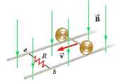
Figure P20.65
Want to see the full answer?
Check out a sample textbook solution
Chapter 20 Solutions
College Physics


- In the circuit of Figure P27.25, the switch S has been open for a long time. It is then suddenly closed. Take = 10.0 V, R1 = 50.0 k, R2 = 100 k, and C = 10.0 F. Determine the time constant (a) before the switch is closed and (b) after the switch is closed. (c) Let the switch be closed at t = 0. Determine the current in the switch as a function of time. Figure P27.25 Problems 25 and 26.arrow_forwardAt one instant, a current of 6.0 A flows through part of a circuit as shown in Figure P33.12. Determine the instantaneous potential difference between points A and B if the current starts to decrease at a constant rate of 1.0 102 A/s. FIGURE P33.12arrow_forwardIn the RC circuit shown in Figure P29.78, an ideal battery with emf and internal resistance r is connected to capacitor C. The switch S is initially open and the capacitor is uncharged. At t = 0, the switch is closed. a. Determine the charge q on the capacitor at time t. b. Find the current in the branch be at time t. What is the current as t goes to infinity?arrow_forward
- Consider a series RC circuit as in Figure P28.38 for which R = 1.00 M, C = 5.00 F, and = 30.0 V. Find (a) the time constant of the circuit and (b) the maximum charge on the capacitor after the switch is thrown closed. (c) Find the current in the resistor 10.0 s after the switch is closed.arrow_forwardFigure P29.60 shows a simple RC circuit with a 2.50-F capacitor, a 3.50-M resistor, a 9.00-V emf, and a switch. What are a. the charge on the capacitor, b. the current in the resistor, c. the rate at which the capacitor is storing energy, and d. the rate at which the battery is delivering energy exactly 7.50 s alter the switch is closed?arrow_forwardIn the circuit of Figure P27.25, the switch S has been open for a long time. It is then suddenly closed. Determine the time constant (a) before the switch is closed and (b) after the switch is closed. (c) Let the switch be closed at t = 0. Determine the current in the switch as a function of time. Figure P27.25 Problems 25 and 26.arrow_forward
- Consider a series RC circuit as in Figure P18.35 for which R = 1.00 M, C = 5.00 F, and = 30.0 V. Find (a) the time constant of the circuit and (b) the maximum charge on the capacitor after the switch is thrown closed. (c) Find the current in the resistor 10.0 s after the switch is closed. Figure P18.35 Problem 35 and 38.arrow_forwardA 1kV battery, a 3 kW resistor, and a 0.50-mF capacitor are connected in series with a switch. What is the current in the circuit at a time interval equal to twice the time constant after the switch has been closed? 0 A 45 mA 3 A 0.33 Aarrow_forwardwo parallel rails with negligible resistance are 10.0 cm apart and are connected by a resistor of resistance R3=5.00Ω . The circuit also contains two metal rods having resistances of R1= 10.0 Ω and R2 = 15.0 Ω sliding along the rails . The rods are pulled away from the resistor at constant speeds of v1= 4.00 m/s and v2= 2.00 m/s, respectively. A uniform magnetic field of magnitude B =0.0100 T is applied perpendicular to the plane of the rails. Determine the current in R3.arrow_forward
- In the circuit diagram R1 = 1760 Ω, R2 = 3130 Ω, C1 = 2.9 μF, C2 = 5.7 μF, and ℰ = 12 V. The switch is closed at t = 0. What is the current in A from the battery when t = 1.018 seconds?arrow_forwardIn the figure R1 = 9.81 kΩ, R2 = 15.4 kΩ, C = 0.433 μF, and the ideal battery has emf ε = 18.0 V. First, the switch is closed a long time so that the steady state is reached. Then the switch is opened at time t = 0. What is the current in resistor 2 at t = 3.60 ms?arrow_forwardIn the figure R₁ = 9.42 kQ, R₂ = 15.7 kQ, C = 0.439 µF, and the ideal battery has emf & = 18.0 V. First, the switch is closed a long time so that the steady state is reached. Then the switch is opened at time t = 0. What is the current in resistor 2 at t = 4.10 ms? Number Units R₁ R₂ Carrow_forward
 Principles of Physics: A Calculus-Based TextPhysicsISBN:9781133104261Author:Raymond A. Serway, John W. JewettPublisher:Cengage Learning
 Physics for Scientists and Engineers: Foundations...PhysicsISBN:9781133939146Author:Katz, Debora M.Publisher:Cengage Learning
 Physics for Scientists and Engineers with Modern ...PhysicsISBN:9781337553292Author:Raymond A. Serway, John W. JewettPublisher:Cengage Learning
 Physics for Scientists and EngineersPhysicsISBN:9781337553278Author:Raymond A. Serway, John W. JewettPublisher:Cengage Learning
 College PhysicsPhysicsISBN:9781285737027Author:Raymond A. Serway, Chris VuillePublisher:Cengage Learning
 College PhysicsPhysicsISBN:9781305952300Author:Raymond A. Serway, Chris VuillePublisher:Cengage Learning