
Tutorials in Introductory Physics
1st Edition
ISBN: 9780130970695
Author: Peter S. Shaffer, Lillian C. McDermott
Publisher: Addison Wesley
expand_more
expand_more
format_list_bulleted
Videos
Textbook Question
Chapter 20.2, Problem 3bTH
b. A student cuts the write between bulbs A and C as shown.
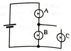
i. Rank bulbs A, B, and C in order of brightness. Explain how you determined your answer.
ii. Rank the voltages across the bulbs. Explain.
iii. Write an equation that relates the voltage across bulbs A and B to the battery voltage.
iv. Is the voltage across bulb Agreater than, less than, or equal to one half the battery voltage? Explain your reasoning.
Expert Solution & Answer
Want to see the full answer?
Check out a sample textbook solution
Students have asked these similar questions
m
2R
R
3. The new symbol you see in the diagram at the left is a multicell battery (like a 9V), which is
made up of a number of smaller single cell batteries (like a 1.5V). Let's say its total voltage is V.
A. Which resistor takes the most voltage?
B.
What is the total resistance?
C.
In variables, what is the current in the circuit?
D.
How does the voltage used by the 2R compare with R?
E. In variables, what is the voltage used by the 2R resistor?
Answer the following questions.
1. Why does the voltage across the resistor for charging and discharging processes
change the sign from positive to negative? Hint: think about the direction of current.
2. Does the voltage V across the resistor for charging and discharging obey by the same
equation: V = Vo eRC
3. What is the sum of the voltages across the capacitor Vc and across the resistor VR at
any point in time during the charging and discharging processes?
Use a snipping tool to copy and paste the waveform chart and graph for the charging and
discharging curves into the lab report.
1. For all practical purposes, a capacitor is considered fully discharged (or fully charged)
after 5 time constants. What is the voltage across a discharging capacitor in a RC circuit
that has V₁ = 10V, and t = 5 t seconds? Show your work
2.
What is the purpose of finding t in a RC circuit?
3. In the virtual simulation, the light bulb is a nice visual indicator of the behavior of a
discharging series RC circuit. However, explain why is it easier to find C using a resistor
instead of a Light Bulb.
Chapter 20 Solutions
Tutorials in Introductory Physics
Ch. 20.1 - In tutorial, you compared the relative brightness...Ch. 20.1 - Use the model for electric current to rank the...Ch. 20.1 - Rang the brightness of the bulbs. Explain your...Ch. 20.1 - A wire is now added to the circuit as shown. i....Ch. 20.1 - Rank the networks according to their equivalent...Ch. 20.1 - How does adding a single bulb to a circuit in...Ch. 20.1 - How does adding a single bulb to a circuit in...Ch. 20.1 - The network AE above are connected, in turn, to...Ch. 20.1 - Rank the bulbs in order from brightest to dimmest....Ch. 20.1 - Suppose that a switch has been added to the...
Ch. 20.2 - The circuit at right consists of a bulb in series...Ch. 20.2 - The circuit at right consists of a bulb in series...Ch. 20.2 - The circuit at right consists of a bulb in series...Ch. 20.2 - In the circuit at right, the voltage across bulb 1...Ch. 20.2 - Prob. 2bTHCh. 20.2 - Box A and box B are now interchanged. It is...Ch. 20.2 - Consider the circuit as shown. i. Rank bulbs A, B,...Ch. 20.2 - b. A student cuts the write between bulbs A and C...Ch. 20.2 - Consider the following discussion between two...Ch. 20.2 - Rank bulbs 16 in order or brightness. Explain your...Ch. 20.2 - Rank the voltages across the bulbs. Explain your...Ch. 20.2 - Write an equation that relates the voltage across...Ch. 20.2 - Bulb 1 is removed from its socket. i. Does the...Ch. 20.3 - Describe the behavior of the bulb in the two...Ch. 20.3 - A second identical bulb is flow added to the...Ch. 20.3 - Just after the switch is closed: • what is the...Ch. 20.3 - A long time after the switch is closed: • rank the...Ch. 20.3 - Summarize your results by describing the behavior...
Additional Science Textbook Solutions
Find more solutions based on key concepts
6.47 A small glider is placed against a compressed spring at the bottom of an air track that slopes upward at a...
University Physics (14th Edition)
Write each number in decimal form.
25. 7.68 × 10⁻¹
Applied Physics (11th Edition)
BIO Power linesdo their magnetic fields pose a risk? Power lines produce both electric and magnetic fields The ...
College Physics
(a) If 2.0 mol of an ideal gas are initially at temperature 250 K and pressure 1.5 atm. whats the gas volume? (...
Essential University Physics: Volume 1 (3rd Edition)
Knowledge Booster


Learn more about
Need a deep-dive on the concept behind this application? Look no further. Learn more about this topic, physics and related others by exploring similar questions and additional content below.Similar questions
- Part B. Finding the PD Directions: Solve the following problems. Write your answer on a clean sheet of paper. Show your solutions. 1. To carry how much charge between two points having potential difference equal to 220 V, 1760 J of work is done? Ans. 8 C 2. The EMF of a cell falls from 3 volts to 2.8 volts when its terminals are joined to an electrical load of 4 Ohms. Calculate the internal resistance of the cell.arrow_forwardTwo 60.0 Ω resistors are connected in parallel and this parallel arrangement is then connected in series with a 30.0 Ω resistor. The combination is placed across a 120. V potential difference. 1.Draw a schematic diagram of the circuit using correct symbols. 2.What is the equivalent resistance of the parallel portion of the circuit? 3.What is the equivalent resistance for the entire circuit? 4.What is the total current in the circuit? 5.What is the voltage drop across the 30.0 Ω resistor? 6.What is the voltage drop across the parallel portion of the circuit? 7.What is the current through each resistor?sarrow_forwardTake three resistors.R1=25 ohms, R2=17 ohms and R3 = 3 ohms. Let V0 = 30 V. Now, connect the resistors as shown in the figure, and connect them to the power supply. Record the voltage across each resistor, using the voltmeter. a. Are the voltages V1, V2 and V3 equal to each other? Why or why not? b. Calculate the total voltage V = V1 + V2 + V3. Explain why it has the value it does. c. Use Ohm’s law to calculate the current through each resistor. d. Calculate the effective resistance of the circuit. e. Construct another circuit by replacing the 3 resistors with the single effective resistance. please solve all points..arrow_forward
- Solve the following problems. Show and COMPLETE solutions. Draw the CIRCUIT DIAGRAM or the equivalent circuit. 1. Three lamps of resistances 5 Ω, 10 Ω and 15 Ω are connected in series. The combination is then connected to a 120-V battery. Find the equivalent resistance of the circuit, the total current in the circuit, the voltage across each lamp, the total power supplied by the battery to the circuit and the power dissipated by each lamp.arrow_forwarda. Draw a circuit with a battery and two identical light bulbs (same resistance) in series. Label all circuit elements and the current using the notation from Figures 1 and 2. b. If the battery voltage is 3V and the light bulb resistance is 150, what is the voltage drop across each of the light bulbs? What is the current going through each bulb?arrow_forwardB. Directions: Read, understand, and perform the tasks by applying what you learned. 1. Make a Venn Diagram comparing emf of a source and potential difference across the circuit. 2. The battery supplies a maximum voltage of 12 V. When it is connected to an external circuit, the voltage measured by the voltmeter across the circuit is only 10 V. Is this possible? Explain your answer. 3. Why do the problems occur when an ammeter is connected in parallel with the lamp?arrow_forward
- 2. Combinations of capacitors. You have three capacitors, 3 μF, 6 μF, and 9 μF. a. What is the equivalent capacitance if they are connected in series? Show your work. b. What is the equivalent capacitance if they are connected in parallel? Show your work.arrow_forwardA 24.0 V battery is wired in parallel with three resistors, R1 = 10.0 Ohms, R2 = 60.0 Ohms, and R3 = 150.0 Ohms. a.) Using either the computer drawing tools or a scanned hand written diagram, draw this circuit including proper symbols and labels. (Do not copy and paste an image from any other resource) b.) Find the equivalent resistance and total current running through the circuit. Show your work and label the current flow on your diagram. c.) Find the current flow and voltage drop through each resistor. Show your work and explain.arrow_forwardA 12.0V battery is wired in series with 3 resistors, 8 Ohm, 15 Ohm and 75 Ohm. a.) Using either the computer drawing tools or a scanned hand written diagram, draw this circuit including proper symbols and labels. (Do not copy and paste an image from any other resource) b.) Find the equivalent resistance and current flowing through each resistor. Show your work and label your diagram with the current amount and direction of flow. GEind the voltage drop, across each resistor in the circuit. Show your work.arrow_forward
- 1. Does the resistance of all substances increase with temperature? Explain. 2. What is the temperature coefficient of resistance, and what are its units? 3. Are the a of a metal conductor and the B of a thermistor the same? Explain. 4. What the circuit conditions when Wheatstone bridge is are a "balanced"? 5. Assuming that B remained constant, what would be the resistance of the thermistor in the experiment as the temperature approached absolute zero? 6. What characteristics of the thermistor make it flexible a temperature transducer?arrow_forwardII. Problem Solving. Answer the following problems. Show your complete solution for each problem on the space provided. 1. When a lightning strikes from the cloud to the ground, current as high as 25,000 amperes can occur and last for about 40µs. How much charge is transferred from the cloud to the ground during such a strike? 2. An aluminum cube has sides of length 1.80 m. What is the resistance between the two opposite faces of the cube?arrow_forwardDirections: Write the letter of your answer on a separate sheet of paper.1. With 21 V applied, if R1 = 5 ohms, R2 = 35 ohms, and R3 = 14 ohms, whatis the current in R2 if R1 is connected in series with the parallel circuit R2and R3?A. 200 mA B. 400 mA C.600 mA D.800 mA 2. What is the total resistance of a circuit when R1 (7 kΩ) is in series with aparallel combination of R2 (20 kΩ), R3 (36 kΩ), and R4 (45 kΩ)?A.4 kΩ B.17 kΩ C. 41 kΩ D. 108 kΩarrow_forward
arrow_back_ios
SEE MORE QUESTIONS
arrow_forward_ios
Recommended textbooks for you
 College PhysicsPhysicsISBN:9781305952300Author:Raymond A. Serway, Chris VuillePublisher:Cengage Learning
 University Physics (14th Edition)PhysicsISBN:9780133969290Author:Hugh D. Young, Roger A. FreedmanPublisher:PEARSON
 Introduction To Quantum MechanicsPhysicsISBN:9781107189638Author:Griffiths, David J., Schroeter, Darrell F.Publisher:Cambridge University Press
 Physics for Scientists and EngineersPhysicsISBN:9781337553278Author:Raymond A. Serway, John W. JewettPublisher:Cengage Learning
 Lecture- Tutorials for Introductory AstronomyPhysicsISBN:9780321820464Author:Edward E. Prather, Tim P. Slater, Jeff P. Adams, Gina BrissendenPublisher:Addison-Wesley
 College Physics: A Strategic Approach (4th Editio...PhysicsISBN:9780134609034Author:Randall D. Knight (Professor Emeritus), Brian Jones, Stuart FieldPublisher:PEARSON
College Physics
Physics
ISBN:9781305952300
Author:Raymond A. Serway, Chris Vuille
Publisher:Cengage Learning
University Physics (14th Edition)
Physics
ISBN:9780133969290
Author:Hugh D. Young, Roger A. Freedman
Publisher:PEARSON
Introduction To Quantum Mechanics
Physics
ISBN:9781107189638
Author:Griffiths, David J., Schroeter, Darrell F.
Publisher:Cambridge University Press
Physics for Scientists and Engineers
Physics
ISBN:9781337553278
Author:Raymond A. Serway, John W. Jewett
Publisher:Cengage Learning
Lecture- Tutorials for Introductory Astronomy
Physics
ISBN:9780321820464
Author:Edward E. Prather, Tim P. Slater, Jeff P. Adams, Gina Brissenden
Publisher:Addison-Wesley
College Physics: A Strategic Approach (4th Editio...
Physics
ISBN:9780134609034
Author:Randall D. Knight (Professor Emeritus), Brian Jones, Stuart Field
Publisher:PEARSON
Series & Parallel - Potential Divider Circuits - GCSE & A-level Physics; Author: Science Shorts;https://www.youtube.com/watch?v=vf8HVTVvsdw;License: Standard YouTube License, CC-BY