
Videos
Describe the behavior of the bulb in the two situations below.
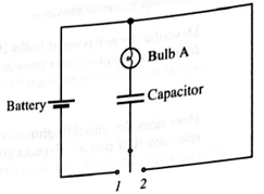
i. The switch is first moved to position 1. Describe the behavior of the bulb from just after the switch is closed until a long time later. Explain.
ii. The switch is now moved to position 2. Describe the behavior of the bulb from just after the switch is closed until a long time later. Explain your reasoning.
(i)
The behavior of the bulb from just after the switch is closed until a long time later in the situation when the switch is first moved to position
Explanation of Solution
Introduction:
Consider the circuit shown in Figure 1.
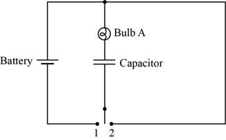
Figure 1
The brightness of the bulb depends upon the current flowing through that bulb. The bulb will be brighter if the flow of current through that bulb is high. In other words, more current passes through less resistance that mean if the resistance is less then bulb will appear brighter.
The circuit diagram when the switch is at position
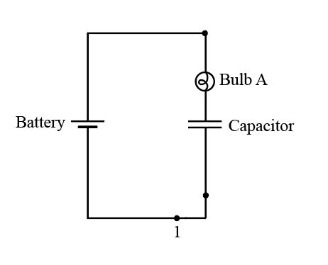
Figure 2
Initially, thecapacitor is short circuited and starts charging slowly. As thecurrent decays with respect to time, the bulb initially glows, but later it goes dimmer with time, and after a long time it stops glowing.
If it stops glowing, the capacitor comes in the open circuit condition and the current flow across it is zero.
Conclusion:
Therefore, the behavior of the bulb from just after the switch is closed until a long time later is described above.
(ii)
The behavior of the bulb from just after the switch is closed until a long time later in the situation when the switch is now moved to position
Explanation of Solution
Introduction:
The brightness of the bulb depends upon the current flowing through that bulb. The bulb will be brighter if the flow of current through that bulb is high. In other words, more current passes through less resistance that mean if the resistance is less then bulb will appear brighter.
The circuit diagram when the switch is at position
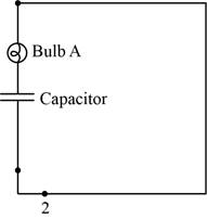
Figure 3
The capacitor voltage is equal to battery voltage at the initial stage.After this, capacitor startsdischarging and the currentdecays with time. So, blub glows bright initially, but thengoes dimmer with time, and after long timeit stops glowing.
If it stops glowing, the capacitor comes in the open circuit condition and the current flow across it is zero.
Conclusion:
Therefore, the behavior of the bulb from just after the switch is closed until a long time later is described above.
Want to see more full solutions like this?
Chapter 20 Solutions
Tutorials in Introductory Physics
Additional Science Textbook Solutions
Physics (5th Edition)
Physics for Scientists and Engineers: A Strategic Approach, Vol. 1 (Chs 1-21) (4th Edition)
College Physics (10th Edition)
Modern Physics
Essential University Physics: Volume 2 (3rd Edition)
Essential University Physics (3rd Edition)


- My answer is incorrect, please write find my wrong in my explanation(process detail). I attach the image of my process of explanation and the professor's process(blue color) 2. When discharging a capacitor in an RC (resistor-capacitor) circuit, the charge Q varies according to the equation:????? +??= 0where R is resistance, C is the capacitance (both constants). Find a function for the charge stored inthe capacitor: (There’s no need to know anything about electronics or physics to do this problem. R and C are just constants—just do the math.)?(?) = _____________________________________________arrow_forwardWrite your response. (300 to 500 words) Discussion: 1. Explain the working of the Incandescent light bulb and how it popularized the use of electricity. 2. Consider what was the impact of the introduction of this technology on human lives in that time period, eg. including a contrast with previous lighting technologies, what was different, what were the benefits, what became possible, any limitations, or disadvantages.arrow_forwardGood afternoon! I am working on problem number 26 in the attached pic. I also sent a pic of where I am getting hung up. If you guys could help me understand what to do next and perhaps give a short explanation as to why, I would greatly appreciate it! Thanks in advance:-)arrow_forward
- I keep getting different answers with each calculation and unsure of where I am going wrong. If possible, please show steps so I may understand where my calculations were incorrect. (a). What's the capacitance of your capacitor? (the value and unit(s)). (b). If you disconnect the battery and separate the plates to a distance of 3.50 cm without discharging them, what will be the potential difference between them? (the value and unit(s)).arrow_forwardPlease good handwriting and clear ideas explaining the process! 4C Solve the highlighted question , if possible help me with the rest! NOTE consider the cross-sectional area of the toroid to be circular.arrow_forwardConsider the circuit configurations below, where two lightbulbs are connected to a single battery in different ways. Based on what you learned about parallel and series connections in lab, which of these two configurations would result in the light bulbs being the brightest? Fully explain your reasoning. Imagine that you are given four 100Ω resistors to build a circuit. Your challenge is to use all four of the resistors in the circuit, but the circuit must have an overall equivalent resistance of 100Ω. Is this possible? If so, draw a diagram of the circuit and explain how the connections result in a 100Ω equivalent resistance. If this is not possible, draw a diagram of a circuit involving all four resistors that has an equivalent resistance as close to 100Ω as is possible.arrow_forward
- Identical bulbs are shown in the circuit. 1) Is bulb A brighter, dimmer, or the same brightness as bulb B? Explain 2) Is the current through bulb D greater that or less that, or equal to the current through bulb F. Explain. 3) If bulb F is unscrewed from its socket, does bulb B become brighter, dimmer, or stay the same. Explain.arrow_forwardSolve the following problems and show your COMPLETE solution.1. Resistors in Series and ParallelFind the equivalent resistance of the network of resistors shown below. This network isusually referred to as resistor ladder. What current will flow through the circuit whenconnected to a 120 V DC supply?arrow_forwardGiven the circuit below: If all the currents flowing through R1, R2, and R3 (I1, I2, and I3, respectively) are going in the top junction, what is the equation resulting from applying the Kirchhoff's loop rule for a clockwise loop around the perimeter of the circuit?arrow_forward
- Please answer the question below. Show all of your work and each step. 1. Shown in yellow in the figure below is a region of the uniform magnetic field of width a=1.18 cm that is used to deflect a beam of accelerated electrons entering this region normally with speed v=11.6 × 10⁶ m/s. After leaving the deflection region, electrons hit the screen, distance b=13.6 cm away, to produce an image. When the field is zero, the electrons would hit the screen in the center, at point O. With the field B=46.3 G, electrons hit the screen at point P, distance d above point O. Find this displacement d caused by the magnetic deflection: d= _____ cmarrow_forwardII. Use the 1st picture as reference for solving, and 2nd picture for answering. Part 1: Obtain the force experience by current-carrying wire with length L2 due to current-carrying wire with length L1? Part 2: Obtain the force experience by current-carrying wire with length L1 due to current-carrying wire with length L2?arrow_forwardDirections: Solve for the given problems. Show your complete solutions.Round off your answers into the proper number of significant figures.2. The current in the wire varies with time according to the relation I = 55 A –(0.65 A/s^2)t^2.a. How many coulombs of charge pass a cross-section of the wire in thetime interval between t = 0 and t = 8.0 s?b. What constant current would transport the same charge in the same time interval?Note: In problem 2, A means ampere, s means second.arrow_forward
 Glencoe Physics: Principles and Problems, Student...PhysicsISBN:9780078807213Author:Paul W. ZitzewitzPublisher:Glencoe/McGraw-Hill