
Introductory Circuit Analysis (13th Edition)
13th Edition
ISBN: 9780133923605
Author: Robert L. Boylestad
Publisher: PEARSON
expand_more
expand_more
format_list_bulleted
Videos
Textbook Question
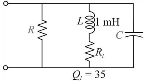
Chapter 21, Problem 17P
The network shown in Fig. 21.58 is to resonate at
Expert Solution & Answer
Want to see the full answer?
Check out a sample textbook solution
Students have asked these similar questions
1. A tuned collector oscillator in radio receiver has a fixed
inductance of 60µH and has to be tunable over the
frequency band of 400 to 1200 kHz. Find the range of
variable capacitor to be used.
2. A Colpitt's oscillator is designed with C = 100 pF and C₂ =
7500 pF. The inductance is variable. Determine the range of
inductance values, if the frequency of oscillation is to vary
between 950 kHz and 2050 kHz.
The buck converter with resistive load has the input voltage of 30[V], the output voltage of 10 [V]
(constant), and the switching frequency of 30 [kHz). If the output average power is 25[W), then
determine the size of the inductor such that the minimum inductor current is 25 % of the average
inductor current.
O 74.07 mikro Henry
O 124.56 mikro Henry
88.89 mikro Henry
O 148.15 mikro Henry
O 118.52 mikro Henry
O 44.44 mikro Henry
O 59.26 mikro Henry
O 32.78 mikro Henry
exam.ptuk.edu.ps/mod/quiz/attemp
Google hil>
YouTu
urse
Referring to the Figure below the input
voltage is 120 Vrms and the frequency 60 Hz, C=
100µF
following question:
1- what is the unfiltered peak full-wave rectified
voltage.
2- Draw the unfiltered peak full-wave rectified.
3- If the frequency of a full-wave rectified voltage
is 120 Hz. Calculate the approximate peak-to peak
ripple voltage at the output.
4- Calculate the approximate de value of the output voltage.
5- Calculate the ripple factor.
and the resistor 5002. answer the
of
tion
10:1
120V
Output
60 Hz
直
5
E
R
Chapter 21 Solutions
Introductory Circuit Analysis (13th Edition)
Ch. 21 - Find the resonant s and fs for the series circuit...Ch. 21 - For the senes circuit in Fig. 21.51 : a. Find the...Ch. 21 - For the senes circuit in Fig. 21.52 : a. Find the...Ch. 21 - For the circuit in Fig. 21.53: a. Find the value...Ch. 21 - a. Find the bandwidth of a series resonant circuit...Ch. 21 - A series circuit has a resonant frequency of 10...Ch. 21 - a. The bandwidth of a series resonant circuit is...Ch. 21 - The cutoff frequencies of a series resonant...Ch. 21 - a. Design a series resonant circuit with an input...Ch. 21 - Design a series resonant circuit to have a...
Ch. 21 - A series resonant circuit is to resonate at s=2106...Ch. 21 - Prob. 12PCh. 21 - For the ideal parallel resonant circuit in Fig. 21...Ch. 21 - For the parallel resonant network in Fig. 21.55:...Ch. 21 - The network of Fig. 21.56 has a supply with an...Ch. 21 - For the network in Fig. 21.57: a. Find the value...Ch. 21 - The network shown in Fig. 21.58 is to resonate at...Ch. 21 - For the network in Fig. 21.59: a. Find the...Ch. 21 - Prob. 19PCh. 21 - It is desired that the impedance ZT of the high Q...Ch. 21 - For the network in Fig. 21.62: a. Find fp. b....Ch. 21 - For the network in Fig. 21.63: a. Find the value...Ch. 21 - Prob. 23PCh. 21 - For the network in Fig. 21.65: a. Find fs. fp, and...Ch. 21 - For the network in Fig. 21.66, the following are...Ch. 21 - Prob. 26PCh. 21 - For the parallel resonant circuit in Fig. 21.68:...Ch. 21 - Verify the results in Example 21.8, That is, show...Ch. 21 - Find fp and fm for the parallel resonant network...
Knowledge Booster


Learn more about
Need a deep-dive on the concept behind this application? Look no further. Learn more about this topic, electrical-engineering and related others by exploring similar questions and additional content below.Similar questions
- Draw the spectrum of the followings modulated signal for the given case: SSB(+) SSB(-)+C DSB LC DSB SC VSB + Carrow_forwardIf the TIME/DIV is set to 0.2 ms, what is the time constant of the circuit? X ms An oscillator with a natural frequency of 380 Hz is driven by a 580 Hz sinusoidal signal. At what frequency does it oscillate?arrow_forwardPower electronics Solve q 13arrow_forward
- A resistor of resistance R=1000 Q is maintained at 17 °C and it shunted by 100 µH inductor. Determine the rms noise voltage across the inductor over a frequency bandwidth of: Ans: 182 x109 volt i) ii) 15.9 kHz 159 kHz Ans: 9.22 x10⁻⁸ volt 111) 1590 kHz Ans: 2.34 x10⁻⁶ voltarrow_forwardFREQUENCY RESPONSE ( NEED NEAT HANDWRITTEN SOLUTION ONLY OTHERWISE DOWNVOTE)arrow_forward28. A tuning coil of negligible resistance is to limit the current through it to a 50 mA when 35 V is applied across it at 500 KHz. Find its inductance. a. 0.2228 microhenry b. 0.2228 millihenry c. 0.4489 henry d. 4487.9895 henryarrow_forward
- A vibration analyst wishes to record a frequency spectrum covering the range 0-10000 Hz with a resolution of 0.5 Hz. Calculate the necessary ADC sampling rate and also the necessary number of samples per spectrum.arrow_forwardH.W: A resistor of resistance R=1000 2is maintained at 17 °C and it shunted by 100 uH inductor. Determine the ms noise voltage across the inductor over a frequency bandwi dth of: Ans: 182 x10° volt Ans: 9.22 x10 volt Ans: 2.34 x10 volt i) 15.9 kHz ii) i) 159 kHz 1590 kHzarrow_forwardFor a transistorized RC oscillator, select the value of capacitor C in order to provide 2 KHz oscillator frequency with resistance Rc=10kOhms, R=8KOhms. Given that Rc = 10 x 10^3 Hz, R = 8 x 10^3Hz, f = 2 x 10^3Hz. Show your solutions. 3 μF 0.003 μ F 3nF 0.3 μFarrow_forward
- Sketch output waveform the following CLIPPER circuits. Please show your solutions/analysis. 3. Sketch ir and Vo for the circuit for the input shown. 10 ka 10 V Si Si 5.3 V 7.3 V. -10 Varrow_forwardTransients: What is the time constant of the following circuit in milliseconds? R₂ R4 ULO Parameters: R₁ = 20 R₂ = 30 R3 = 10 R₁ = 50 L = 2mH Answer: R1 R3 1arrow_forwardIt refers to the mixing of frequencies in a nonlinear device or the use of nonlinear mixing to convert one frequency to another. Select your answer. Frequency transformation Frequency mixing Superheterodyne Heterodynearrow_forward
arrow_back_ios
SEE MORE QUESTIONS
arrow_forward_ios
Recommended textbooks for you
 Introductory Circuit Analysis (13th Edition)Electrical EngineeringISBN:9780133923605Author:Robert L. BoylestadPublisher:PEARSON
 Delmar's Standard Textbook Of ElectricityElectrical EngineeringISBN:9781337900348Author:Stephen L. HermanPublisher:Cengage Learning
 Programmable Logic ControllersElectrical EngineeringISBN:9780073373843Author:Frank D. PetruzellaPublisher:McGraw-Hill Education
 Fundamentals of Electric CircuitsElectrical EngineeringISBN:9780078028229Author:Charles K Alexander, Matthew SadikuPublisher:McGraw-Hill Education
 Electric Circuits. (11th Edition)Electrical EngineeringISBN:9780134746968Author:James W. Nilsson, Susan RiedelPublisher:PEARSON
 Engineering ElectromagneticsElectrical EngineeringISBN:9780078028151Author:Hayt, William H. (william Hart), Jr, BUCK, John A.Publisher:Mcgraw-hill Education,
Introductory Circuit Analysis (13th Edition)
Electrical Engineering
ISBN:9780133923605
Author:Robert L. Boylestad
Publisher:PEARSON
Delmar's Standard Textbook Of Electricity
Electrical Engineering
ISBN:9781337900348
Author:Stephen L. Herman
Publisher:Cengage Learning
Programmable Logic Controllers
Electrical Engineering
ISBN:9780073373843
Author:Frank D. Petruzella
Publisher:McGraw-Hill Education
Fundamentals of Electric Circuits
Electrical Engineering
ISBN:9780078028229
Author:Charles K Alexander, Matthew Sadiku
Publisher:McGraw-Hill Education
Electric Circuits. (11th Edition)
Electrical Engineering
ISBN:9780134746968
Author:James W. Nilsson, Susan Riedel
Publisher:PEARSON
Engineering Electromagnetics
Electrical Engineering
ISBN:9780078028151
Author:Hayt, William H. (william Hart), Jr, BUCK, John A.
Publisher:Mcgraw-hill Education,
David Sarnoff, Howard Armstrong & the Superheterodyne Receiver; Author: Kathy Loves Physics & History;https://www.youtube.com/watch?v=7eTfF67Ka5w;License: Standard Youtube License