
Videos
- A switch has a variable resistance that is nearly zero when closed and extremely large when open, and it is placed in series with the device it controls. Explain the effect the switch in Figure 21.43 has on current when open and when closed.
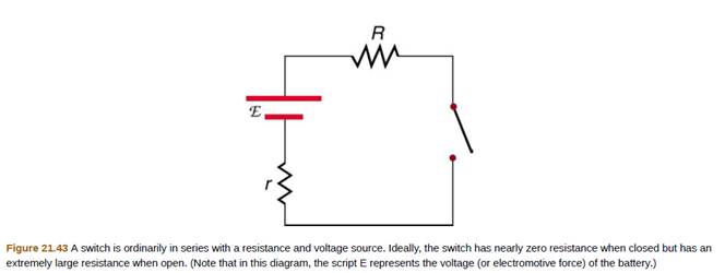
The effect of switch on current when open and closed.
Answer to Problem 1CQ
Current increases from zero to some constant value as the switch is closed from initial open state.
Explanation of Solution
Given:
Resistance of the switch when closed
Resistance of switch when open
Emf of the battery
Internal resistance of the battery
External resistance connected in series with battery
Current in the circuit when switch is closed
Current in the circuit when switch is open
Formula Used:
Equivalent resistance in series is given as
According to ohm's law
Calculation:
When the switch is open:
Equivalent resistance in series of the circuit given as
Using ohm's law, current in the circuit is given as
Since,
When the switch is closed:
Equivalent resistance in series of the circuit given as
Using ohm's law, current in the circuit is given as
Since
Clearly
Conclusion:
When switch is closed, there is some constant value of current in the circuit and when the circuit is open, there is no current in the circuit.
Want to see more full solutions like this?
Chapter 21 Solutions
College Physics
Additional Science Textbook Solutions
Physics for Scientists and Engineers: A Strategic Approach with Modern Physics (4th Edition)
College Physics: A Strategic Approach (3rd Edition)
Sears And Zemansky's University Physics With Modern Physics
Conceptual Physics (12th Edition)
Physics: Principles with Applications
College Physics: A Strategic Approach (4th Edition)


- With the switch in the circuit of Figure 21.18a open, there is no current in R2. There is current in R1, however, and it is measured with the ammeter at the right side of the circuit. If the switch is closed (Fig. 21.18b), there is current in R2. What happens to the reading on the ammeter when the switch is closed? (a) The reading increases. (b) The reading decreases. (c) The reading does not change.arrow_forwardThe switch is closed in Figure 18.20. After a long time compared with the time constant, of the circuit, what will the current be in the 2- resistor? (a) 4 A (b) 3 A (c) 2 A (d) 1 A (c) More information is needed. Figure 18.20 (Quick Quiz 18.9)arrow_forwardThe switch S in Figure 20.27 is closed at t = 0 and the current at a reference time tref 0 is Iref. If the circuit is changed as, described below and the switch is again dosed at t = 0, determine whether the current I at the same time would be greater than, less than, or equal to the original value of Iref. Indicate your answers wilt G. L. or E, respectively. (a) Both the battery voltage and the resistance R are doubled. (b) The inductance L b doubled. (c) The battery voltage . the resistance R, and the inductance L are each doubled. Figure 20.27 A series RL circuit. As the current increases toward its maximum value, the inductor produces an emf that opposes the increasing current.arrow_forward
- Consider the circuit in Figure 21.29 and assume the batter has no internal resistance. (i) Just after the switch is closed, what is the current in the battery? (a) 0 (b) /2R (c) 2/R (d) /R (e) impossible to determine (ii) After a very long time, what is the current in the battery? Choose from the same choices.arrow_forwardFigure P18.37 shows a simplified model of a cardiac defibrillator, a device used to patients in ventricular fibrillation. When the switch S is toggled to the left, the capacitor C charges through the resistor R .When the switch is toggled to the right, the capacitor discharges current through the patients torso, modeled as the resistor Rtorso, allowing the hearts normal rhythm to be reestablished. (a) If the capacitor is initially uncharged with C = 8.00 F and = 1250 V, find the value of R required to charge the capacitor to a voltage of 775 V in 1.50 s. (b) If the capacitor is then discharged across the patients torso with, Rtorso = 1250 , calculate the voltage across the capacitor after 5.00 ms. Figure P18.37arrow_forwardThe switch S in Figure 20.27 is closed at t = 0 and the current at a reference time tref 0 is Iref. If the circuit is changed as, described below and the switch is again dosed at t = 0, determine whether the current I at the same time would be greater than, less than, or equal to the original value of Iref. Indicate your answers wilt G. L. or E, respectively. (a) Both the battery voltage and the resistance R are doubled. (b) The inductance L b doubled. (c) The battery voltage . the resistance R, and the inductance L are each doubled. Figure 20.27 A series RL circuit. As the current increases toward its maximum value, the inductor produces an emf that opposes the increasing current.arrow_forward
- Consider the circuit below, (a) What is the initial current through resistor R2? when the switch is closed? (b) What is die current through resistor R2 when the capacitor is fully charged, long after die switch is closed? (c) What happens if the switch is opened after it has been closed for some rime? (d) If the switch has been closed for a time period long enough for the capacitor to become fully charged, and then the switch is opened, how long before the current through resistor R1 reaches half of its initial value?arrow_forwardWhen the switch is open in Figure 18.8, power Po is delivered to the resistor R1. When the switch is closed, which of the following is true about the power Pc delivered to R1? (Neglect the internal resistance of the battery.) (a) Pc Po (b) Pc = Po (c) Pc Po Figure 18.8 (Quick Quizzes 18.5 and 18.6)arrow_forwardWhen the switch is open in Figure 18.8, power Po is delivered to the resistor R1. When the switch is closed, which of the following is true about the power Pc delivered to R1? (Neglect the internal resistance of the battery.) (a) Pc Po (b) Pc = Po (c) Pc Po Figure 18.8 (Quick Quizzes 18.5 and 18.6)arrow_forward
- Figure P18.37 shows a simplified model of a cardiac defibrillator, a device used to patients in ventricular fibrillation. When the switch S is toggled to the left, the capacitor C charges through the resistor R .When the switch is toggled to the right, the capacitor discharges current through the patients torso, modeled as the resistor Rtorso, allowing the hearts normal rhythm to be reestablished. (a) If the capacitor is initially uncharged with C = 8.00 F and = 1250 V, find the value of R required to charge the capacitor to a voltage of 775 V in 1.50 s. (b) If the capacitor is then discharged across the patients torso with, Rtorso = 1250 , calculate the voltage across the capacitor after 5.00 ms. Figure P18.37arrow_forwardA 240-kV power transmission line carrying 5.00x10². A is hung from grounded metal towers by ceramic insulators, each having a 1.00x 10⁹- resistance. Figure 21.51. (a) What is the resistance to ground of 100 of these insulators? (b) Calculate the power dissipated by 100 of them, (c) What fraction of the power carried by the line is this? Explicitly show how you follow the steps in the Problem-Solving Strategies for Series and Parallel Resistors.arrow_forwardThe human body can exhibit a wide range of resistances to current depending on the path of the current, contact area, and sweatiness of the skin. Suppose the resistance across the chest from the left hand to the right hand is 1.0 106 . (a) How much voltage is required to cause possible heart fibrillation in a man, which corresponds to 500 mA of direct current? (b) Why should rubber-soled shoes and rubber gloves be worn when working around electricity?arrow_forward
 Principles of Physics: A Calculus-Based TextPhysicsISBN:9781133104261Author:Raymond A. Serway, John W. JewettPublisher:Cengage Learning
 College PhysicsPhysicsISBN:9781285737027Author:Raymond A. Serway, Chris VuillePublisher:Cengage Learning
 College PhysicsPhysicsISBN:9781305952300Author:Raymond A. Serway, Chris VuillePublisher:Cengage Learning
 College PhysicsPhysicsISBN:9781938168000Author:Paul Peter Urone, Roger HinrichsPublisher:OpenStax College
 Physics for Scientists and Engineers, Technology ...PhysicsISBN:9781305116399Author:Raymond A. Serway, John W. JewettPublisher:Cengage Learning