
Concept explainers
Videos
The rod ABC is made of an aluminum for which E = 70 GPa. Knowing that P = 6 kN and Q = 42 kN, determine the deflection of (a) point A, (b) point B.
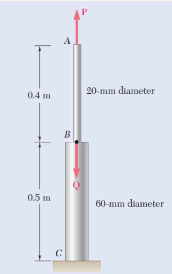
Fig. P2.19 and P2.20
a)
The deflection of the point A
Answer to Problem 20P
The deflection of the point A
Explanation of Solution
Given information:
The Young’s modulus of the aluminium (E) is
The force at the point A (P) is
The force at the point B (Q) is
The diameter of the rod AB
The diameter of the rod BC
The length of the rod AB
The length of the rod BC
Calculation:
Calculate the cross-sectional area of the rod AB
Substitute
Calculate the cross-sectional area of the rod BC
Substitute
Calculate the defection of the rod AB
Substitute
Calculate the defection of the rod BC
Substitute
Calculate the deflection of the point A
Substitute
Hence, the deflection of the point A
b)
The deflection of point the B
Answer to Problem 20P
The deflection of the B
Explanation of Solution
Given information:
The Young’s modulus of the aluminium (E) is
The force at the point A (P) is
The force at the point B (Q) is
The diameter of the rod AB
The diameter of the rod BC
The length of the rod AB
The length of the rod BC
Calculation:
Calculate the cross-sectional area of the rod AB
Substitute
Calculate the cross-sectional area of the rod BC
Substitute
Calculate the defection of the rod AB
Substitute
Calculate the defection of the rod BC
Substitute
The deflection of the point B
Therefore, the deflection of the point B
Want to see more full solutions like this?
Chapter 2 Solutions
Mechanics of Materials, 7th Edition


- = P2.39 Two cylindrical rods, AC made of aluminum and CD made of steel, are joined at C and restrained by rigid supports at A and D. For the loading shown and knowing that Ea 10.4 × 10⁶ psi and Es = 29 × 106 psi, determine (a) the reactions at A and D, (b) the deflection of point C. -8 in.- E A 1-¹-in. diameter Fig. P2.39 10 in.-10 in.. B. 18 kips C D 14 kips 15-in. diameterarrow_forward2.41 Two cylindrical rods, one of steel and the other of brass, are joined at C and restrained by rigid supports at A and E. For the loading shown and knowing that E, = 200 GPa and E, = 105 GPa, deter- mine (a) the reactions at A and E, (b) the deflection of point C. Dimensions in mm 100 100 -150--120- A DI E Steel B. Brass 60 kN 40 kN 40-mm diam. 30-mm diam. Fig. P2.41arrow_forwardT ). 2.19 Both portions of the rod ABC are made of an aluminum for which E = 70 GPa. Knowing that the magnitude of P is 4 kN, determine (a) the value of Q so that the deflection at A is zero, (b) the cor- responding deflection of B. 0.4 m 0.5 m A B C P 20-mm diameter 60-mm diameter Fig. P2.19 and P2.20 C Fig. P2.18 50 kipsarrow_forward
- Portion BC of the rod ABC are made of an aluminum for which E= 70 GPa and portion AB is made of steel for which E = 200 GPa. Given: P = 9 kN, a = 0.6 m, b=0.7 m and the diameter of rod AB is c = 36 mm, (a) Determine the value of Q so that the deflection at A is zero (b) The corresponding deflection of point B 60-mm diameterarrow_forward2. The length of the 2-mm-diameter steel wire CD has been adjusted so that, with no load applied, a gap of 1.5 mm exists between the end Bof the rigid beam ACB and a contact point E. load should be applied to the beam to cause contact between B and E. Using E = 200 GPa, determine where a 225-N 250 mm 225 N 1.5 mm B C A 360 mm 90 mmarrow_forwardTwo cylindrical rods, one of steel and the other of brass, are joined at C and restrained by rigid supports at A and E. The steel rod has a length of 300 mm while the brass rod has a length of 200 mm. The diameters of the rods are shown in the figure below. A force of 60 kN is applied at point B of the steel segment. For the loading shown and knowing that modulus of elasticity values for steel and brass are respectively Es = 200 GPa and Eb = 105 GPa, determine a.) The reactions at A and E: RA and RE. b.) The deflection of point C from its original location. how to doarrow_forward
- Q1. The steel rod AC and brass rod CD are rigidly joined at C. The loads acting are P=60 kN and Q=80 kN. Disregarding the weight of the rods, determine the deflection of (a) point C (b) point D. Given E=200 GPa for steel; E=105 GPa for brass. 2 m B D=40 mm D=25 mm D to 2 m 3 marrow_forward2. Link BD is made of brass ( E = 103 GPa ) and has a cross-sectional area of 258 mm?. Link CE is made of aluminum ( E = 72 GPa ) and has a cross sectional area of 332 mm? . Determine the maximum force P that can be applied vertically at point A if the deflection of A is not to exceed 0.30 mm. 225 mm 150 mm -225 mm 125 mmarrow_forward2.5 m 3.5 m -4.0 m Fig. P2.13arrow_forward
- 2.14 The aluminum rod ABC (E 10.1 × 10⁶ psi), which consists of two cylindrical portions AB and BC, is to be replaced with a cylin- drical steel rod DE (E = 29 × 106 psi) of the same overall length. Determine the minimum required diameter d of the steel rod if its vertical deformation is not to exceed the deformation of the aluminum rod under the same load and if the allowable stress in the steel rod is not to exceed 24 ksi. Ĵ 12 in. + 18 in. 28 kips -1.5 in. Fig. P2.14 B -2.25 in. 28 kips D E --arrow_forwardThe rod ABC is made of an aluminum for which E = 71.15 GPa. Knowing that P=10.2 kN and Q=51.62kN, determine the deflection (in um) of point B y=0.46 and z=0.56. Round off the final answer in four decimal places.arrow_forward4) Each of the links AB and CD is made of aluminum (E =75 GPa) and has a cross-sectional area of 125 mm². Knowing that they support the rigid member BC, determine the deflection of point E A D P = 5 kN 0.36 m В C 0.44 m 0.20 marrow_forward
 Elements Of ElectromagneticsMechanical EngineeringISBN:9780190698614Author:Sadiku, Matthew N. O.Publisher:Oxford University Press
 Mechanics of Materials (10th Edition)Mechanical EngineeringISBN:9780134319650Author:Russell C. HibbelerPublisher:PEARSON
 Thermodynamics: An Engineering ApproachMechanical EngineeringISBN:9781259822674Author:Yunus A. Cengel Dr., Michael A. BolesPublisher:McGraw-Hill Education
 Control Systems EngineeringMechanical EngineeringISBN:9781118170519Author:Norman S. NisePublisher:WILEY
 Mechanics of Materials (MindTap Course List)Mechanical EngineeringISBN:9781337093347Author:Barry J. Goodno, James M. GerePublisher:Cengage Learning
 Engineering Mechanics: StaticsMechanical EngineeringISBN:9781118807330Author:James L. Meriam, L. G. Kraige, J. N. BoltonPublisher:WILEY