Videos
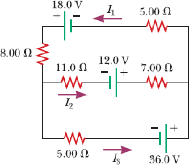
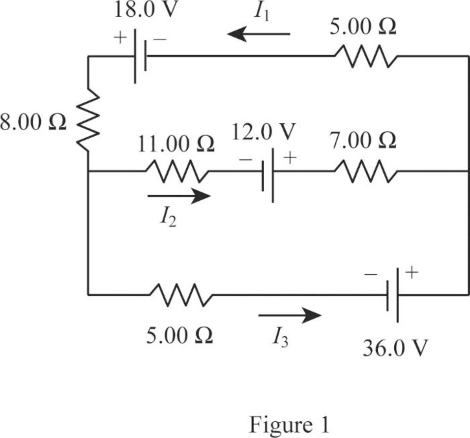
For the circuit shown in Figure P21.50, we wish to find the currents I1, I2, and I3. Use Kirchhoff’s rules to obtain equations for (a) the upper loop, (b) the lower loop, and (c) the junction on the left side. In each case, suppress units for clarity and simplify, combining the terms. (d) Solve the junction equation for I3. (e) Using the equation found in part (d), eliminate I3 from the equation found in part (b). (f) Solve the equations found in parts (a) and (e) simultaneously for the two unknowns I1 and I2. (g) Substitute the answers found in part (f) into the junction equation found in part (d), solving for I3. (h) What is the significance of the negative answer for I2?
Figure P21.50
(a)
The equations for the upper loop in the circuit diagram.
Answer to Problem 50P
The equation for the upper loop is
Explanation of Solution
Write the expression for the Kirchhoff’s loop rule for the upper loop going counter clockwise.
Conclusion:
Therefore, the equation for the upper loop is
(b)
The equations for the lower loop in the circuit diagram.
Answer to Problem 50P
The equation for the lower loop is
Explanation of Solution
Write the expression for the Kirchhoff’s loop rule for the lower loop going counter clockwise.
Conclusion:
Therefore, the equation for the lower loop is
(c)
The equation of the junction on the left side in the circuit diagram.
Answer to Problem 50P
The equation of the junction in the left side is
Explanation of Solution
Write the expression for the Kirchhoff’s junction rule for the junction on the left side in the circuit.
Conclusion:
Therefore, the equation of the junction in the left side is
(d)
The equation for
Answer to Problem 50P
The equation for
Explanation of Solution
Use equation (III) to solve for
Conclusion:
Therefore, the equation for
(e)
The equation of the lower loop without using
Answer to Problem 50P
The equation of the lower loop without using
Explanation of Solution
Use equation (IV) in (II) to solve for the lower without using
Conclusion:
Therefore, the equation of the lower loop without using
(f)
The value of current
Answer to Problem 50P
The value of current
Explanation of Solution
Use equation (V) to solve for
Use equation (VI) in (I) to solve for
Use equation (VII) in (I) to solve for
Conclusion:
Therefore, the value of current
(g)
The value of current
Answer to Problem 50P
The value of current
Explanation of Solution
Use equation (VIII) and (VII) in (IV) to solve for
Conclusion:
Therefore, the value of current
(h)
The significance of negative sign in the current
Answer to Problem 50P
The negative sign for
Explanation of Solution
The negative sign in the value of the current
Conclusion:
Therefore, the negative sign for
Want to see more full solutions like this?
Chapter 21 Solutions
Principles of Physics: A Calculus-Based Text


- A student makes a homemade resistor from a graphite pencil 5.00 cm long, where the graphite is 0.05 mm indiameter. The resistivity of the graphite is =1.38102/m . The homemade resistor is place inseries with a switch, a 10.00-mF capacitor and a 0.50-V power source, (a) What is the BC time constant of the circuit? (b) What is the potential drop across the pencil 1.00 s after the switch is closed?arrow_forwardConsider the circuit shown. Assume that the battery connected is ideal. Let V = 16V, C = 2µF , R1 = 1kN, and R2 = R3 = R4 = kN. s1 R2 c1 v1 R1 R4 R3 a) Time Constant. Solve for the time constant of the circuit. Express your final answer in seconds. b) Charging. Suppose the capacitor is initially uncharged and the switch is closed at t = Os. What would be the charge inside the capacitor at t = 3.5 ms? Express your final answer in Coulombs.arrow_forwardYou take a 6.34 V battery, a 226 kQ resistor, and an uncharged capacitor to put together a series circuit. You connect the battery and after 21.2 seconds the current in the circuit has fallen to 61% of its initial value. What is the value of the capacitor in microfarads (µF)? (Enter answer as an integer. Do not enter unit.) A Click Submit to complete this assessment. «< Question 2 of 2arrow_forward
- Give the symbolic expression for the emf E using KVL for the circuit with S1 closed and S2 open. Give your answer in terms of the current I, resistor R, capacitors C1 and C2 and charges stored in the respective capacitors Q1 and Q2. Use * to denote product and / to denote division. So to group the product of, say, a and b_1 write a*b_1. And to write a ratio of say, c_1 and d write c_1/d. To add the product and ratio write a*b_1 + c_1/d . a)Write the mathematical expression for emf E. E= In the figure there's a circuit with an emf E=21V, two resistors R1=35kΩ and R2=5.5kΩ, two capacitors C1=25μF and C2=22μF and two switches S1 and S2. b) Find the time constant for this configuration of the circuit. Time constant τ c) Find how much charge will be stored in C2 after time t=1.3τ seconds. Charge stored in C2 PartII After t=10τ seconds, we open switch S1 and close switch S2. Mark current time as t′=0. In this configuration, capacitor C2 discharges through the resistor R2. d) Find…arrow_forwardGiven the circuit and currents i1=0.026A, i2=-0.0142A, and i3=0.0154, Find change in voltage from point A to point F. Find through short (VA->E->F) and long (VA->B->C->F) ways. Answer in units of Volts. Hints: Use Kirckoff's Laws. Answer should be +9.0741V for both ways.arrow_forwardIn Figure 2, &1 = 5.00 kV, E2 = 4.50 kV, E3 = 3.50 kV, R1 = 650.0 Q, R450.0 Ω, R 540.0 Ω, R4150.0 Ω and Rs = 230.0 Ω. 2. %3D Using Kirchhoff's Laws, calculate the currents I,, Iz and I3. Assume that the batteries have negligible internal resistance. R1 I3 R2 I1 Ez R3 13 I2 R5 E2 R4 Figure 2arrow_forward
- Which statements are true? a) At any junction point in a circuit, the sum of all the currents entering the junction must equal the sum of all the currents leaving the junction. b) The sum of the changes in potential around any closed loop of a circuit must equal zero. c) Kirchoff's junction rule is based on the conservation of energy. d) Kirchoff's loop rule is based on the conservation of charge.arrow_forwardCan you help with sub question 9B 9a. What is the time constant for this circuit? 9B. What is the charge on the capacitor after the switch has been closed for t = 2.32×10⁻² s?arrow_forwardIn a parallel electrical circuit, the same current flows through each component, whereas the potential drop across each component can be different. Select one: O True O Falsearrow_forward
- A 2 0 resistor, a 10 N resistor, and a 15 N resistor are connected in parallel across a 12 V battery. Determine the equivalent resistance for the circuit. Answer in units of N. 026 (part 2 of 2) . b) Determine the current in the circuit. Answer in units of A.arrow_forward210 0 a 24 V 50 μ 320 0 First, what is the time constant of the circuit formed when a and c are connected? Give your ans in ms to 3 significant digits. Question 17 Next, what is the time constant of the circuit formed when b and c connected? Give your answe ms to 3 significant digits. Question 18 Finally, you perform the following sequence of events. The capacitor starts uncharged and the switch is flipped to connect a and c. The capacitor is charged for 20 ms. The switch is then flipp to connect b and c, and the capacitor is discharged for 26 ms, at which time the switch is set to position where it is not in contact with either a or b. What is the voltage on the capacitor? Give answer to 2 significant digits.arrow_forwardIn the following circuit, lo = 0.171 A, I, = 0.043 A, and I2 = 0.129 A. Find the potential difference from A to B going along the following paths (show all work): a) Through the battery and the 20 Q resistor on the bottom. b) Through the resistors in the middle (40 Q and 20 Q). c) Through the 20 Q resistor on the far right. A 40 O 6V 20 Ω 20 2 20 2 MacBook Pro B.arrow_forward
 Principles of Physics: A Calculus-Based TextPhysicsISBN:9781133104261Author:Raymond A. Serway, John W. JewettPublisher:Cengage Learning