
Engineering Mechanics: Statics & Dynamics (14th Edition)
14th Edition
ISBN: 9780133915426
Author: Russell C. Hibbeler
Publisher: PEARSON
expand_more
expand_more
format_list_bulleted
Concept explainers
Videos
Textbook Question
Chapter 2.3, Problem 5P
Solve  with F = 350 lb.
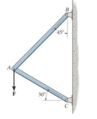
Prob. 2-4/5
Expert Solution & Answer
Want to see the full answer?
Check out a sample textbook solution
Students have asked these similar questions
4-6 if possible
3 Solve it, and draw a free body diagram.
Solve with free body diagram.
Chapter 2 Solutions
Engineering Mechanics: Statics & Dynamics (14th Edition)
Ch. 2.3 - In each case, construct the parallelogram law to...Ch. 2.3 - In each case, show how to resolve the force F into...Ch. 2.3 - Determine the magnitude of the resultant force...Ch. 2.3 - Two forces act on the hook. Determine the...Ch. 2.3 - Determine the magnitude of the resultant force and...Ch. 2.3 - Resolve the 30-lb force into components along the...Ch. 2.3 - The force F = 450 lb acts on the frame. Resolve...Ch. 2.3 - If force F is to have a component along the u axis...Ch. 2.3 - If = 60 and F = 450 N, determine the magnitude of...Ch. 2.3 - If the magnitude of the resultant force is to be...
Ch. 2.3 - Determine the magnitude of the resultant force FR...Ch. 2.3 - The vertical force F acts downward at A on the...Ch. 2.3 - Solve with F = 350 lb. Prob. 2-4/5Ch. 2.3 - Determine the magnitude of the resultant force FR...Ch. 2.3 - Resolve the force F1 into components acting along...Ch. 2.3 - Resolve the force F2 into components acting along...Ch. 2.3 - If the resultant force acting on the support is to...Ch. 2.3 - Determine the magnitude of the resultant force and...Ch. 2.3 - The plate is subjected to the two forces at A and...Ch. 2.3 - Determine the angle for connecting member A to...Ch. 2.3 - The force acting on the gear tooth is F = 20lb....Ch. 2.3 - The component of force F acting along line aa is...Ch. 2.3 - Force F acts on the frame such that its component...Ch. 2.3 - Force F acts on the frame such that its component...Ch. 2.3 - Determine the magnitude and direction of the...Ch. 2.3 - Determine the magnitude and direction of the...Ch. 2.3 - Determine the design angle (0 90) for strut AB...Ch. 2.3 - Determine the design angle (0 90) between...Ch. 2.3 - Determine the magnitude and direction of the...Ch. 2.3 - Prob. 22PCh. 2.3 - Prob. 23PCh. 2.3 - Prob. 24PCh. 2.3 - If F1 = 30 lb and F2 = 40 lb, determine the angles...Ch. 2.3 - Determine the magnitude and direction of FA SO...Ch. 2.3 - Determine the magnitude and direction, measured...Ch. 2.3 - Determine the magnitude of force F so that the...Ch. 2.3 - If the resultant force of the two tugboats is 3...Ch. 2.3 - If FB = 3 kN and = 45, determine the magnitude of...Ch. 2.3 - If the resultant force of the two tugboats is...Ch. 2.4 - Resolve each force acting on the post into its x...Ch. 2.4 - Determine the magnitude and direction of the...Ch. 2.4 - Prob. 9FPCh. 2.4 - If the resultant force acting on the bracket is to...Ch. 2.4 - If the magnitude of the resultant force acting on...Ch. 2.4 - Determine the magnitude of the resultant force and...Ch. 2.4 - Determine the magnitude of the resultant force and...Ch. 2.4 - Prob. 33PCh. 2.4 - Prob. 34PCh. 2.4 - Determine the magnitude of the resultant force and...Ch. 2.4 - Resolve each force acting on the gusset plate into...Ch. 2.4 - Determine the magnitude of the resultant force...Ch. 2.4 - Prob. 38PCh. 2.4 - Prob. 39PCh. 2.4 - Determine the magnitude of the resultant force and...Ch. 2.4 - Determine the magnitude of the resultant force and...Ch. 2.4 - Express F1, F2, and F3 as Cartesian vectors.Ch. 2.4 - Prob. 43PCh. 2.4 - Prob. 44PCh. 2.4 - Prob. 45PCh. 2.4 - Determine the magnitude and orientation of FB so...Ch. 2.4 - Determine the magnitude and orientation. measured...Ch. 2.4 - Prob. 48PCh. 2.4 - Prob. 49PCh. 2.4 - Express F1, F2, and F3 as Cartesian vectors.Ch. 2.4 - Prob. 51PCh. 2.4 - Prob. 52PCh. 2.4 - Prob. 53PCh. 2.4 - Prob. 54PCh. 2.4 - Prob. 55PCh. 2.4 - Prob. 56PCh. 2.4 - If the resultant force acting on the bracket is...Ch. 2.4 - Prob. 58PCh. 2.4 - If F = 5 kN and = 30, determine the magnitude of...Ch. 2.6 - Sketch the following forces on the x, y, z...Ch. 2.6 - In each case, establish F as a Cartesian vector,...Ch. 2.6 - Show how to resolve each force into its x, y, z...Ch. 2.6 - Determine the coordinate direction angles of the...Ch. 2.6 - Prob. 14FPCh. 2.6 - Prob. 15FPCh. 2.6 - Prob. 16FPCh. 2.6 - Prob. 17FPCh. 2.6 - Prob. 18FPCh. 2.6 - The force F has a magnitude of 80 lb and acts...Ch. 2.6 - Prob. 61PCh. 2.6 - Prob. 62PCh. 2.6 - Prob. 63PCh. 2.6 - Prob. 64PCh. 2.6 - The screw eye is subjected to the two forces...Ch. 2.6 - Prob. 66PCh. 2.6 - Determine the magnitude and coordinate direction...Ch. 2.6 - Determine the magnitude and coordinate direction...Ch. 2.6 - Determine the magnitude and coordinate direction...Ch. 2.6 - Determine the magnitude and coordinate direction...Ch. 2.6 - Specify the magnitude and coordinate direction...Ch. 2.6 - Prob. 72PCh. 2.6 - Prob. 73PCh. 2.6 - Prob. 74PCh. 2.6 - Prob. 75PCh. 2.6 - Prob. 76PCh. 2.6 - Prob. 77PCh. 2.6 - Prob. 78PCh. 2.6 - Determine the coordinate direction angles of the...Ch. 2.6 - The bracket is subjected to the two forces shown....Ch. 2.6 - Prob. 81PCh. 2.6 - Prob. 82PCh. 2.6 - If the direction of the resultant force acting on...Ch. 2.6 - Prob. 84PCh. 2.6 - The pole is subjected to the force F which has...Ch. 2.8 - In each case, establish a position vector from...Ch. 2.8 - In each case, express F as a Cartesian vector....Ch. 2.8 - Express the position vector rAB in Cartesian...Ch. 2.8 - Prob. 20FPCh. 2.8 - Express the force as a Cartesian vector. Prob....Ch. 2.8 - Prob. 22FPCh. 2.8 - Prob. 23FPCh. 2.8 - Prob. 24FPCh. 2.8 - Determine the length of the connecting rod AB by...Ch. 2.8 - Express force F as a Cartesian vector; then...Ch. 2.8 - Prob. 88PCh. 2.8 - Prob. 89PCh. 2.8 - Prob. 90PCh. 2.8 - Prob. 91PCh. 2.8 - Prob. 92PCh. 2.8 - If FB = 560 N and FC = 700 N, determine the...Ch. 2.8 - If FB = 700 N, and FC = 560 N, determine the...Ch. 2.8 - The plate is suspended using the three cables...Ch. 2.8 - The three supporting cables exert the forces shown...Ch. 2.8 - Determine the magnitude and coordinate direction...Ch. 2.8 - Prob. 98PCh. 2.8 - Prob. 99PCh. 2.8 - Prob. 100PCh. 2.8 - The two mooring cables exert forces on the stern...Ch. 2.8 - Prob. 102PCh. 2.8 - Determine the magnitude and coordinate direction...Ch. 2.8 - If the force in each cable tied to the bin is 70...Ch. 2.8 - If the resultant of the four forces is FR = {360k}...Ch. 2.9 - P2.8. in each case set up the dot product to find...Ch. 2.9 - Prob. 9PPCh. 2.9 - Prob. 25FPCh. 2.9 - Determine the angle between the force and the...Ch. 2.9 - Prob. 27FPCh. 2.9 - Prob. 28FPCh. 2.9 - Find the magnitude of the projected component of...Ch. 2.9 - Prob. 30FPCh. 2.9 - Determine the magnitudes of the components of the...Ch. 2.9 - Prob. 106PCh. 2.9 - Prob. 107PCh. 2.9 - Prob. 108PCh. 2.9 - Prob. 109PCh. 2.9 - Prob. 110PCh. 2.9 - Prob. 111PCh. 2.9 - Prob. 112PCh. 2.9 - Determine the magnitudes of the components of F =...Ch. 2.9 - Prob. 114PCh. 2.9 - Prob. 115PCh. 2.9 - Prob. 116PCh. 2.9 - Determine the magnitudes of the projected...Ch. 2.9 - Determine the angle between cables AB and AC....Ch. 2.9 - Prob. 119PCh. 2.9 - Prob. 120PCh. 2.9 - Determine the angle between the two cables...Ch. 2.9 - Determine the angle between the cables AB and AC....Ch. 2.9 - Determine the magnitude of the projected component...Ch. 2.9 - Determine the magnitude of the projected component...Ch. 2.9 - Determine the magnitude of the projection of force...Ch. 2.9 - Prob. 126PCh. 2.9 - Prob. 127PCh. 2.9 - Prob. 128PCh. 2.9 - Determine the magnitude of the projected component...Ch. 2.9 - Prob. 130PCh. 2.9 - Prob. 131PCh. 2.9 - Determine the magnitude of the projected component...Ch. 2.9 - Prob. 133PCh. 2.9 - Prob. 134PCh. 2.9 - Prob. 135PCh. 2.9 - Prob. 136PCh. 2.9 - Prob. 137PCh. 2.9 - Prob. 138PCh. 2.9 - Prob. 139PCh. 2.9 - Determine the magnitude of the resultant force FR...Ch. 2.9 - Resolve F into components along the u and v axes...Ch. 2.9 - Prob. 3RPCh. 2.9 - The cable at the end of the crane boom exerts a...Ch. 2.9 - Prob. 5RPCh. 2.9 - Prob. 6RPCh. 2.9 - Prob. 7RPCh. 2.9 - Prob. 8RP
Knowledge Booster


Learn more about
Need a deep-dive on the concept behind this application? Look no further. Learn more about this topic, mechanical-engineering and related others by exploring similar questions and additional content below.Similar questions
- Solve with complete Free Body Diagram.arrow_forwardH.W Forces F1 and F2 act on the bracket as shown, Find R. F- 100 N 30 F- 80 Narrow_forwardPulley A delivers a steady torque of 1100 lb-in. To a pump through its shaft at C. The tension in the lower side of the belt is 165 lb. The driving motor weighs 200 lb and rotates clockwise. Determine the bearing reaction force at O. A 9" B 30° 37 8" 150 lb - 5"-- 5"-arrow_forward
- Practice Problem 3: Solve for the resultant force. F = 500 lb 30 45° F= 800 lbarrow_forwardQ5/A) From the figure below, determine the reaction force at pin C. A 000 0.6 m 10 kN 0.6 m 0.8 m 60° 0.4 m 6 kN OBarrow_forwardThe figure shows a wire cutter. Determine the cutting force on the wire at A when the 75-N forces are applied to the handgrips. (Hint: The horizontal components of pin forces at B and D are zero due to symmetry.)arrow_forward
- Given the figure determine the bar force at BD and ABarrow_forward4/106 In the special position shown for the log hoist, booms AF and EG are at right angles to one an- other and AF is perpendicular to AB. If the hoist is handling a log weighing 4800 lb, compute the forces supported by the pins at A and D in this one position due to the weight of the log. E 10 A 45° 12 8 12" 24" 12arrow_forwardThe round stepped shaft (diameters d and D) shown below is a design for an exoplanet rover wheel axle. Assuming the wheel is stuck, a torque from the motor is transmitted to the axle but it is not rotating. The reaction of the weight of the rover on the ground and the torque the wheel applies to the ground are represented by the force F acting in the center of the wheel hub (not shown) at point C. There is a sharp fillet at B with radius r shown below. Bearings are shown at point A and next to point B. You may assume the bearing at B resists the bending moment caused by the force F and acts like a fixed reaction. В A L2 L1 T L3 - ØD Ød R. r F SUBMIT ANSWERS HERE: Paramete Parameter Value Value SUT (tension) 400 MPa | L1 400 mm Suc (Compression) 600 Мра L2 200 mm Sy 380 MPа L3 100 mm 600 N-m ø d 40 mm F 0.2 kN ø D 55 mm R. r 8 mmarrow_forward
arrow_back_ios
SEE MORE QUESTIONS
arrow_forward_ios
Recommended textbooks for you
 International Edition---engineering Mechanics: St...Mechanical EngineeringISBN:9781305501607Author:Andrew Pytel And Jaan KiusalaasPublisher:CENGAGE L
International Edition---engineering Mechanics: St...
Mechanical Engineering
ISBN:9781305501607
Author:Andrew Pytel And Jaan Kiusalaas
Publisher:CENGAGE L
EVERYTHING on Axial Loading Normal Stress in 10 MINUTES - Mechanics of Materials; Author: Less Boring Lectures;https://www.youtube.com/watch?v=jQ-fNqZWrNg;License: Standard YouTube License, CC-BY