
Loose Leaf for Engineering Circuit Analysis Format: Loose-leaf
9th Edition
ISBN: 9781259989452
Author: Hayt
Publisher: Mcgraw Hill Publishers
expand_more
expand_more
format_list_bulleted
Concept explainers
Videos
Textbook Question
Chapter 2.4, Problem 13P
The power absorbed by the resistor if i = 3 nA and R = 4.7 MΩ.
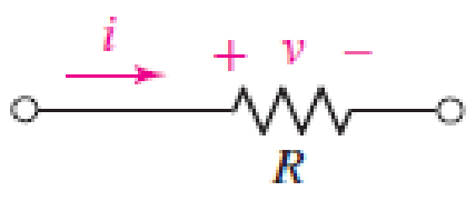
■ FIGURE 2.25
Expert Solution & Answer
Want to see the full answer?
Check out a sample textbook solution
Students have asked these similar questions
BASIC ELECTRICITY (EE116)
2- For each of the following resistors; write the color bands.
(d) R= 560 kn ± 10%
(e) R= 0.150 ± 5%
(f) R=49 MN ± 5%
EXPERIMENT 1
7
2110
From the given figure, determine the
following:
R₁, R2, R3
I1, I2, I3
V₁, V2, V3
P₁, P2, P3
RT, IT, VT, PT
1922
292
HUF
24 volts
3Ω
ww
A charge is given as
O = t3 + 6t + 1
Coulombs. Calculate for the current in
Amperes as the charges flow in 2 seconds.
None of the above
O 1.64
O 2.82
O 5.81
O 5.25
Chapter 2 Solutions
Loose Leaf for Engineering Circuit Analysis Format: Loose-leaf
Ch. 2.1 - A krypton fluoride laser emits light at a...Ch. 2.1 - A typical incandescent reading lamp runs at 60 W....Ch. 2.2 - In the wire of Fig. 2.7, electrons are moving left...Ch. 2.2 - For the element in Fig. 2.11, v1 = 17 V. Determine...Ch. 2.2 - Prob. 6PCh. 2.2 - Determine the power being generated by the circuit...Ch. 2.2 - Determine the power being delivered to the circuit...Ch. 2.2 - Your rechargeable smartphone battery has a voltage...Ch. 2.3 - Find the power absorbed by each element in the...Ch. 2.4 - Prob. 11P
Ch. 2.4 - Prob. 12PCh. 2.4 - The power absorbed by the resistor if i = 3 nA and...Ch. 2 - Convert the following to engineering notation: (a)...Ch. 2 - Convert the following to engineering notation:...Ch. 2 - Prob. 3ECh. 2 - Prob. 4ECh. 2 - Convert the following to SI units, taking care to...Ch. 2 - Prob. 6ECh. 2 - It takes you approximately 2 hours to finish your...Ch. 2 - A certain krypton fluoride laser generates 15 ns...Ch. 2 - Your recommended daily food intake is 2500 food...Ch. 2 - An electric vehicle is driven by a single motor...Ch. 2 - Under insolation conditions of 500 W/m2 (direct...Ch. 2 - A certain metal oxide nanowire piezoelectricity...Ch. 2 - Assuming a global population of 9 billion people,...Ch. 2 - The total charge flowing out of one end of a small...Ch. 2 - Prob. 15ECh. 2 - The total charge stored on a 1 cm diameter...Ch. 2 - A mysterious device found in a forgotten...Ch. 2 - A new type of device appears to accumulate charge...Ch. 2 - The current flowing through a tungsten-filament...Ch. 2 - The current waveform depicted in Fig. 2.28 is...Ch. 2 - The current waveform depicted in Fig. 2.29 is...Ch. 2 - A wind power system with increasing windspeed has...Ch. 2 - Two metallic terminals protrude from a device. The...Ch. 2 - The convention for voltmeters is to use a black...Ch. 2 - Determine the power absorbed by each of the...Ch. 2 - Determine the power absorbed by each of the...Ch. 2 - Determine the unknown current for the circuit in...Ch. 2 - A constant current of 1 ampere is measured flowing...Ch. 2 - Determine the power supplied by the leftmost...Ch. 2 - The currentvoltage characteristic of a silicon...Ch. 2 - A particular electric utility charges customers...Ch. 2 - The Tilting Windmill Electrical Cooperative LLC...Ch. 2 - A laptop computer consumes an average power of 20...Ch. 2 - You have just installed a rooftop solar...Ch. 2 - Prob. 35ECh. 2 - Some of the ideal sources in the circuit of Fig....Ch. 2 - Prob. 37ECh. 2 - Refer to the circuit represented in Fig. 2.35,...Ch. 2 - Prob. 39ECh. 2 - Prob. 40ECh. 2 - Prob. 41ECh. 2 - Determine the magnitude of the current flowing...Ch. 2 - Real resistors can only be manufactured to a...Ch. 2 - (a) Sketch the current-voltage relationship...Ch. 2 - Prob. 45ECh. 2 - Figure 2.38 depicts the currentvoltage...Ch. 2 - Examine the I-V characteristics in Fig. 2.38....Ch. 2 - Determine the conductance (in siemens) of the...Ch. 2 - Determine the magnitude of the current flowing...Ch. 2 - A 1% tolerance 1 k resistor may in reality have a...Ch. 2 - Utilize the fact that in the circuit of Fig. 2.39,...Ch. 2 - For the circuit in Fig. 2.39, suppose that the...Ch. 2 - For each of the circuits in Fig. 2.40, find the...Ch. 2 - Sketch the power absorbed by a 100 resistor as a...Ch. 2 - You built an android that has a subcircuit...Ch. 2 - Using the data in Table 2.4, calculate the...Ch. 2 - Prob. 58ECh. 2 - Prob. 59ECh. 2 - Prob. 60ECh. 2 - The resistance values in Table 2.4 are calibrated...Ch. 2 - Prob. 62ECh. 2 - Prob. 63ECh. 2 - The network shown in Fig. 2.42 can be used to...Ch. 2 - Prob. 65ECh. 2 - An LED operates at a current of 40 mA, with a...Ch. 2 - You have found a way to directly power your wall...
Knowledge Booster


Learn more about
Need a deep-dive on the concept behind this application? Look no further. Learn more about this topic, electrical-engineering and related others by exploring similar questions and additional content below.Similar questions
- Determine whether the following sequences are energy, power or neitherarrow_forwardDetermine all the nodal voltages and currents for each element in Figure 2, show that ∑?? = 0.arrow_forwardQ2/ in an experiment measuring the internal resistance of a voltmeter you have the following readings Calculate the magnitude of each 1- The electromotive force of the continuous source E 2- The value of the internal resistance of the voltmeter Rv R(O)V(v 1000 2.25 2000 1.8 3000 1.5 4000 1.28 5000 1.12 6000 1 7000 0.9 8000 0.81 9000 0.75arrow_forward
- A coil 4.40 cm in radius, containing 460 turns, is placed in a uniform magnetic field that varies with time according to B=( 1.20x10⁻² T/s)t+(2.95x10-5 T/s4 )t¹. The coil is connected to a 680 2 resistor, and its plane is perpendicular to the magnetic field. You can ignore the resistance of the coil.arrow_forward4 4G !:: اليوم تحرير Question 10 O out of 1 points Two charges of - Q are I cm apart. If one of the charges is replaced by a charge of +2Q, the magnitude of the force between them i one of the chores is renlaced l a dwer of-arrow_forwardQ No. 3: Calculate the potential difference between points m and n shown in Figure 3. 4 V 30 103 12 V ww 50 Figure 3arrow_forward
- 4. Referring to Figure 3 determine The voltage, V1. ii. i. The current through each inductor, I1 and I2. 20 1 30 50 V 6 µF 4H ll 0.5 H Figure 3arrow_forwardDetermine the current in the battery (I1) and then determine the current of each resistor (Let R= 6.234) (please write properly and please show complete solution)arrow_forward12 13 R1 E2 R3 R2 E1 For the circuit shown above, the emf of the batteries and the resistances are listed below. %3D 81 = 77 V, 82 = 5 V, R1 = 8 Q, R2 = 70, R3 = 23 Q. %3D %3D Determine /2=? Please express your answer in units of Amperes (A) with two decimal places. If you a find a negative value, please don't forget the minus sign. www wwarrow_forward
- 4. An electric motor (with an efficiency of n1 = 90%) drives a belt (n2 = 85%) that is connected to a generator (n3 = 92%) that produces electricity for an incandescent light (n4 = 5%). The overall efficiency of the system is therefore: O 90% O 5% O 92% Ο η1χη2x η3χ η4arrow_forward49 When 7A current is flowing in electric circuit then the electric potential difference between B B and C will be. volt. 7A A ww 492 1092 www wwwww 292 502 wwwww 7A (A) 16 (C) 8 (B) 10 (D) 5arrow_forward25 mA 150 Ω 330 2270 225 mA Figure 2.arrow_forward
arrow_back_ios
SEE MORE QUESTIONS
arrow_forward_ios
Recommended textbooks for you
 Introductory Circuit Analysis (13th Edition)Electrical EngineeringISBN:9780133923605Author:Robert L. BoylestadPublisher:PEARSON
 Delmar's Standard Textbook Of ElectricityElectrical EngineeringISBN:9781337900348Author:Stephen L. HermanPublisher:Cengage Learning
 Programmable Logic ControllersElectrical EngineeringISBN:9780073373843Author:Frank D. PetruzellaPublisher:McGraw-Hill Education
 Fundamentals of Electric CircuitsElectrical EngineeringISBN:9780078028229Author:Charles K Alexander, Matthew SadikuPublisher:McGraw-Hill Education
 Electric Circuits. (11th Edition)Electrical EngineeringISBN:9780134746968Author:James W. Nilsson, Susan RiedelPublisher:PEARSON
 Engineering ElectromagneticsElectrical EngineeringISBN:9780078028151Author:Hayt, William H. (william Hart), Jr, BUCK, John A.Publisher:Mcgraw-hill Education,
Introductory Circuit Analysis (13th Edition)
Electrical Engineering
ISBN:9780133923605
Author:Robert L. Boylestad
Publisher:PEARSON
Delmar's Standard Textbook Of Electricity
Electrical Engineering
ISBN:9781337900348
Author:Stephen L. Herman
Publisher:Cengage Learning
Programmable Logic Controllers
Electrical Engineering
ISBN:9780073373843
Author:Frank D. Petruzella
Publisher:McGraw-Hill Education
Fundamentals of Electric Circuits
Electrical Engineering
ISBN:9780078028229
Author:Charles K Alexander, Matthew Sadiku
Publisher:McGraw-Hill Education
Electric Circuits. (11th Edition)
Electrical Engineering
ISBN:9780134746968
Author:James W. Nilsson, Susan Riedel
Publisher:PEARSON
Engineering Electromagnetics
Electrical Engineering
ISBN:9780078028151
Author:Hayt, William H. (william Hart), Jr, BUCK, John A.
Publisher:Mcgraw-hill Education,
What is an electric furnace and how does it work?; Author: Fire & Ice Heating and Air Conditioning Inc;https://www.youtube.com/watch?v=wjAWecPGi0M;License: Standard Youtube License