
Videos
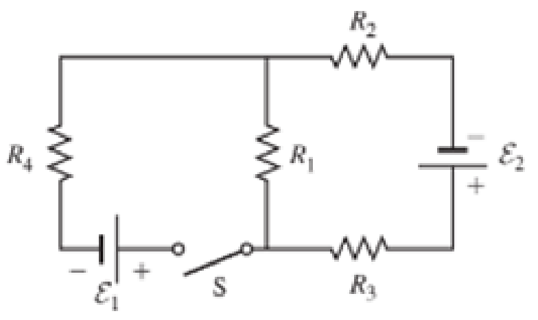
The emfs in Figure P29.43 are ε1 = 6.00 V and ε2 = 12.0 V. The resistances are R1 = 15.0 Ω, R2 = 30.0 Ω, R3 = 45.0 Ω, and R4 = 60.0 Ω. Find the current in each resistor when the switch is
- a. open and
- b. closed.
(a)
The current in each resistor when the switch is open.
Answer to Problem 43PQ
The current flowing through the resistor
Explanation of Solution
As the switch is kept open; the current in the wire EFAB will be zero as the circuit is disconnected.
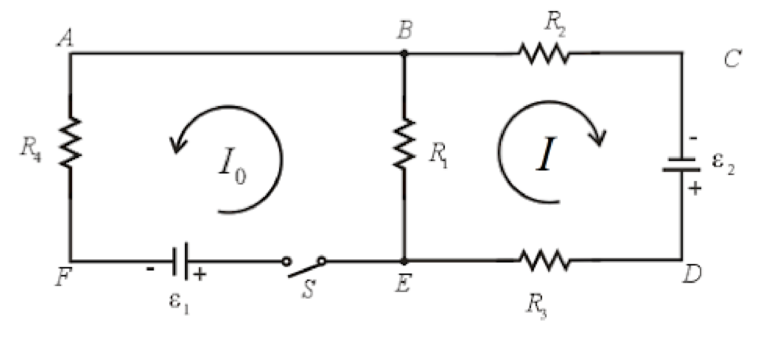
The resistors in the loop BCDEB are connected in series. The current flowing in all the elements in a series circuit is constant.
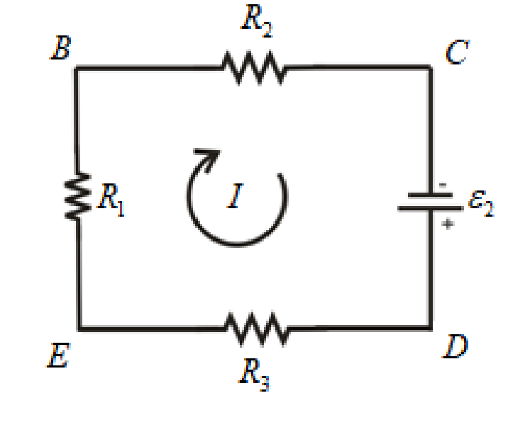
Write the expression for the equivalent resistance in the loop BCDEB as.
Here,
Write the expression for the current in the loop BCDEB as.
Here,
No current flows through the resistor
Conclusion:
Substitute
Substitute
Thus, the current flowing through the resistor
(b)
The current in each resistor when the switch is closed.
Answer to Problem 43PQ
The current flowing through the resistor
Explanation of Solution
The switch is closed, the current starts flowing through all the resistors in the circuit.
The circuit diagram for the closed switch is shown below.
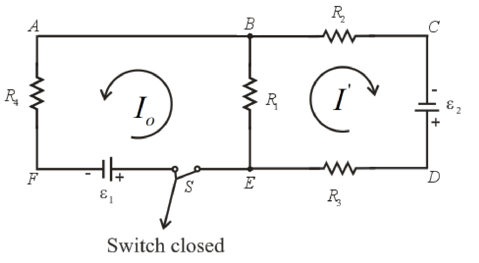
Write the expression for the Kirchhoff’s voltage law in loop ABCDEFA.
Here,
Write the expression for the Kirchhoff’s voltage law in loop ABEFA.
Write the expression for the current through resistor
Here,
Write the expression for the current through resistor
Here,
Write the expression for the current through resistor
Here,
Write the expression for the current through resistor
Here,
Conclusion:
Substitute
Rearrange the above equation for
Substitute
Substitute
Rearrange the above expression for
Substitute
Substitute
Substitute
Substitute
Substitute
Thus, the current flowing through the resistor
Want to see more full solutions like this?
Chapter 29 Solutions
EBK PHYSICS FOR SCIENTISTS AND ENGINEER


- The emfs in the figure below are & = 5.00 V and Ɛ2 = 18.0 V. The resistances are R1 = 17.5 0, R2 = 32. N, R3 = 46.0 N, and R4 = 59.0 N. Find the magnitude of the current in each resistor when the switch is in the following states. R2 R4 R1 S R3 (а) оpen I = A I2 = A I3 = A I4 = A (b) closed I = A I2 = A I3 = A I4 = Aarrow_forwardA 5 μF capacitor is charged by connecting it in series with a 1.0 MΩ resistor and a 30 V battery. Determine a. the time constant of the circuit. b. the current in the resistor 10.0 s after the switch is closed.arrow_forward20. Seven resistors are connected to 20-V dc battery with resistor R, = 10 Q and R, = 10000000 N, and R1 << R2. If the switch S is closed, compute for the effective resistance? Hint: A resistor with relatively very large resistance acts as an open circuit. R, А. 20 0 R, R2 B. 40 Q R, Vpc Voc С. 50 0 R2 D. 10000000 N R, E. 20000000 Q R,arrow_forward
- 15V a. + AM 10.2. 4 t=0 um 45² 652 im + V 1 ic (t) b. Assume switch has been closed for Find a mathematical expression for Vc it capacitor is initially uncharged and the switch is closed at t = 0. Sketch Vc lt). 20m F a long time. opening Fird an expression for ic immediately after the switch and sketch it.arrow_forwardIn the circuits shown below, C = 5.00 µC, R = 10.0 MN and ɛ = 12.0 V. when the switch is closed for 25.0 seconds, the voltage across the resistor is: O a. 8.00 V O b. 6.00 V 10.0 V O d. 2.40 V O e. 1.60 Varrow_forwardthe total resistance is 30.0 kΩ and the circuit is connected to a 24.0 V. The value of the time constant is 34 µs. i. Calculate the total capacitance of the circuit. ii. Calculate the time it takes for the voltage across the resistor to reach 16.0 V after the switch S is closed.arrow_forward
- Problem 5. In the figure below, find I1, l2, and I3 if switch S is (a) open and (b) closed. Ans: (a) I1 = 0.20 A, I2 = 0.20 A, and l3 = 0; (b) I1 = 0.93 A, I2 = -0.44 A, and l3 = -1.37 A 12.0 V 9.0 V d 4.0 2 -M- b 7.02 8.0 Qarrow_forwardIn the circuit diagram R1 = 1760 Ω, R2 = 3130 Ω, C1 = 2.9 μF, C2 = 5.7 μF, and ℰ = 12 V. The switch is closed at t = 0. What is the current in A from the battery when t = 1.018 seconds?arrow_forwardIn the circuit shown. C switch S is closed and at the instant that the current in the circuit drops to 30% of its initial value, find the charge on C. = 3.0 µF and C2 = 4.0 µF are initially uncharged and ɛ = 12 V. After the HH a. 6.6 uC b. 14.4 uC C. 12.6 µC d. 8.4 uC Next page W-arrow_forward
- 10.0 pF 3. In the circuit below each capacitor initially has a charge of magnitude 3.50 nC on its plates. After the switch S is closed, what will be the current in the circuit at the instant that the capacitors have lost 80.0% of their initial stored energy? 20.0. pF 25.0 0 15.0 pFarrow_forwardA) S1 The switch S, is closed for a long time in the circuit shown. Then, S, is opened and Sz is closed simultaneously. What is the maximum charge that can be stored in E the capacitor? ɛ = 30 V, L = 4 mH, R = 5 Q, C = 6 µF L R 0.35 mc None of them 0.65 mC 0.93 C 0.35C 0.65 C 0.93 mcarrow_forwardSoru 5 A B C D E R1 E. F 8 2 4 10 6 R2 R3 R4 S 1 A Seçimi Boş Bırakmak İstiyorum h In the circuit shown on the left are R₁ = 392, R₂ = 292, R3 = 492, and 192. When the switch S is closed, if the voltage across R₁ is RA VR₁ = 42 V, how much current (in Amperes) is read in the ammeter wwwwwwwwwww A?arrow_forward
 Physics for Scientists and Engineers: Foundations...PhysicsISBN:9781133939146Author:Katz, Debora M.Publisher:Cengage Learning