
Concept explainers
Videos
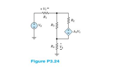
Use nodal analysis on the circuit in Figure P3.24 todetermine the voltage
Want to see the full answer?
Check out a sample textbook solution
Chapter 3 Solutions
Principles and Applications of Electrical Engineering


- O Given the information appearing in the Figure, Fird the level of resistance for Ri e R3. RI 3 o 14V Rgarrow_forwardUsing mesh analysis to the circuit in the figure below, i, can be obtained approximately as? 14V + 10V Select one: 392 ww a. 4.4615 A b. 5.3077 A c. 0.8462 A d.-5.3077 A www 492 www iz 292arrow_forwardCalculate the lx current using the constant voltage model for the circuit in the figure. Circuit Parameters / Vx=12 V, VD ON=800 mV, R1=1.3 k2 Vx D1 VD a. 13.354 mA O b. 10.769 mA O c. 8.615 mA O d. 15.938 mA e. 6.462 mAarrow_forward
- PROBLEM 4. In the circuit below, R3 = 10 k2. Calculate the steady-state voltage across each circuit element. -20V R3 www R2 -5kQ C1 :6μF R1 >8kQarrow_forwardQ3. The circuit to study is shown in figure below, where V1 = 100/0° V, V2 = 50/60° V, and R₁ = 3 Q, R₂ = 50, R3 = 2, R4 = 50, R5 = 50, L5 = 12.8 mH, L6 = 6.4 mH ,C₂= 796µF and C3=796uF assume f=50Hz V1 R1 R5 R2 + Vx & L5 Monote R3 L6 mo V2 C3 R4 a) Apply the mesh current method to obtain a complete set of circuit equations, presenting your answer in matrix form; b) Compute the potential across and the current flowing through the L6 elements.arrow_forward8-13 E (a) Formulate mesh-current equations for the cir- cuit in Figure P3-13. (b) Formulate node-voltage equations for the circuit in Figure P3-13. (c) Which set of equations would be easier to solve? Why? (d) Using MATLAB, find , and i, in terms of the mesh- current variables. SSarrow_forward
- (c) For the network of Figure Q4 (c), R = 700 , L=7 H, C= 1/7 F, Calculate the characteristic roots of the circuit. R L ell V C Figure Q4 (c)arrow_forwardProblem F3 Design a value for R,, R, and Res such that 0.5 mA can be delivered to loads up to 18k Veco Vcc oL Rcs R1 Vcco- V+ R2 Vcc / -Vcc Q1 V- 15V /-15V R2 Lo-Vcc RLoad +arrow_forwardRefer to the given circuit below. Using Superposition Theorem, determine the percent contribution of E1 to the current through R3 (Ibc).arrow_forward
- 3.1 Evaluate the following circuit and determine the following: Given: C1=10uF, C2=20UF, C3= 13UF, C4= 15uF, C5= 9uF, V=300 V C2 C1 C3 C5 C4arrow_forward6. A Thevenin de equivalent circuit always consists of an equivalent.. a. AC voltage source b. capacitance c. DC voltage source d, resistance 7. The superposition theorem is useful for the analysis of. ***** a. single-source circuits. b. only two-source circuits. c. multi-source circuits. d. no source circuits.arrow_forwardQ5. Find the v.(t) in the circuit as shown in Figure Q5 if v.(t) =2V and i(0)=1A. 1F e"u(t) A 1 H Figure Q5 ele ww ww-arrow_forward
 Introductory Circuit Analysis (13th Edition)Electrical EngineeringISBN:9780133923605Author:Robert L. BoylestadPublisher:PEARSON
 Delmar's Standard Textbook Of ElectricityElectrical EngineeringISBN:9781337900348Author:Stephen L. HermanPublisher:Cengage Learning
 Programmable Logic ControllersElectrical EngineeringISBN:9780073373843Author:Frank D. PetruzellaPublisher:McGraw-Hill Education
 Fundamentals of Electric CircuitsElectrical EngineeringISBN:9780078028229Author:Charles K Alexander, Matthew SadikuPublisher:McGraw-Hill Education
 Electric Circuits. (11th Edition)Electrical EngineeringISBN:9780134746968Author:James W. Nilsson, Susan RiedelPublisher:PEARSON
 Engineering ElectromagneticsElectrical EngineeringISBN:9780078028151Author:Hayt, William H. (william Hart), Jr, BUCK, John A.Publisher:Mcgraw-hill Education,