
Concept explainers
Videos
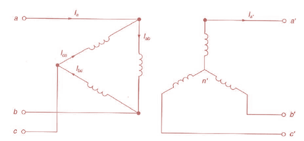
Consider three ideal single-phase transformers (with a voltage gain of
(a) Would such relationships hold for the line voltages as well?
(b) Looking into the current relationships, express
(C) Let

Trending nowThis is a popular solution!

Chapter 3 Solutions
Power System Analysis and Design (MindTap Course List)


- Consider the three single-phase two-winding transformers shown in Figure 3.37. The high-voltage windings are connected in Y. (a) For the low-voltage side, connect the windings in , place the polarity marks, and label the terminals a, b, and c in accordance with the American standard. (b) Relabel the terminals a, b, and c such that VAN is 90 out of phase with Va for positive sequence.arrow_forwardAn ideal transformer has no real or reactive power loss. (a) True (b) Falsearrow_forward5.In three-phase transformers, the high voltage star connection is preferred. This is so because in this case A) The voltage on the star windings is lower than if they were in delta and this reduces manufacturing costs. B) The voltage on the star windings is higher than if they were in delta and this reduces manufacturing costs. C) The voltage on the star windings would be the line-to-line voltage of the system since it is a three-phase manufacturing transformer. D) THERE IS NO SOLUTIONarrow_forward
- 6.5% ans ex A so kvA. 2o00/20 V, So He single-phase transformar has impedance drof of8% and resistance drop of 4%. Caleulate. The Requlation of the Thams former at full- Load o8 P.s Legging. also find The Power factor at which Voltage requlation will Be Zero. Sols 0.5 leading. s alculate The % Noltege Requlation af atransformar in w hich the Percantage resistance drof is 1% and Percentage dre is 6% when The Power fador is 0.8 lagging ) > unity aMS 38 % ans 1 % (シ→ 0.8 leading . amS - 2.2%arrow_forwardChapman Problem 3-4. A single-phase power system is shown in the figure below. The power source feeds a 100-kVA, 14/2.4-kV transformer through a feeder impedance of 38.2 + j140 N. The transformer's equivalent series impedance referred to its low-voltage is 0.12 + j0.5 N. The load on the transformer is 90 kW at 0.85 PF lagging and 2300V. а. What is the voltage at the power source of the system? b. What is the voltage regulation of the transformer? How efficient is the overall power system? С.arrow_forwardA three-phase transformer is given. The number of turns of the high voltage winding is N1=850 and the number of turns of the low voltage winding is N2=34. The high voltage winding is energized with V1= 10 kV rms line-to-line and V2= 400 V rms line-to-line has been taken from the low voltage winding. What is the connection of the low voltage winding if the high voltage winding is Y-connected? *arrow_forward
- Problem 5 Consider a three winding transformer with the following particulars: = Z₁ Z2 Z3 =0.02 + j0.08 £, V₂ = 400 V, 12 = 60/30° A, and I3 = 50/-40° A. Assume that V₂ is the reference phasor, calculate: The intermediate voltage Vo. a. b. The primary current I₁ and the primary voltage V₁. c. The tertiary voltage V3 referred to the primary side. d. The apparent powers and the power factors at the primary, secondary and tertiary terminals. e. The transformer efficiency.arrow_forwardProblem #3: An Ideal transformer circuit diagram is shown below. Find I1, 2, V1, and V2 values. 1: 3 I 2 reonarrow_forwardA single-phase, 240 kVA, 240/4800 V transformer has the parameters shown in Figure Q5. Determine I and V at the primary and secondary when transformer is operating at full load kVA, 0.8 power factor leading and 220 V at the primary side. Find the voltage regulation. Use actual values and per unit system. 0.002625 Q 0.009 0 1.05 Ω 3.6 Ω V2 40 0 30 Q Figure Q5arrow_forward
- 10 A three-phase transformer is given. The number of turns of the high voltage winding is N1=850 and the number of turns of the low voltage winding is N2=34. The high voltage winding is energized with V1= 10 kV rms line-to-line and V2= 400 V rms line-to-line has been taken from the low voltage winding. What is the connection of the low voltage winding if the high voltage winding is Y-connected? Εισαγάγετε την απάντησή σαςarrow_forwardA 4 kVA, 400/200 V single-phase transformer has resistance of 0.02 p.u. and reactance of 0.06 p.u. Its actual resistance and reactance refferd to h.v. side are ?arrow_forwardIn the circuit in Figure 2, the capacitor connected to the a-b terminals of the transformer anda circuit consisting of resistance is defined as a load circuit. a)Find the average power spent by the load circuit? b) How much of the average power calculated in a) by the resistance in the load circuit and how muchspent by the capacitor? Comment on the results obtained?arrow_forward
 Power System Analysis and Design (MindTap Course ...Electrical EngineeringISBN:9781305632134Author:J. Duncan Glover, Thomas Overbye, Mulukutla S. SarmaPublisher:Cengage Learning