
System Dynamics
3rd Edition
ISBN: 9780073398068
Author: III William J. Palm
Publisher: MCG
expand_more
expand_more
format_list_bulleted
Videos
Textbook Question
Chapter 3, Problem 3.38P
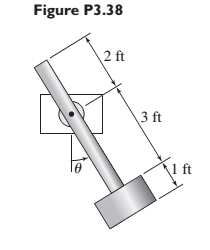
The pendulum shown in Figure P3.38 consists of a slender rod weighing 3 lb and a block weighing 10 lb.
- Determine the location of the center of mass.
Expert Solution & Answer
Want to see the full answer?
Check out a sample textbook solution
Students have asked these similar questions
1. The PASCO human arm model is configured such that
the cord representing the bicep is perfectly vertical and
the forearm is at 90° (in the figure to the right, the cord
is not quite vertical). A mass of 100 g is attached to the
hand. Draw a free-body diagram on the figure to the
right showing all forces which act on the forearm.
The force of the bicep F on the arm
The force of the humerus FH on the arm
The weight of the forearm W
The mass in the hand Wm
100 g
Be careful to draw the force vectors with tails beginning at the point where the force is actually
applied to the forearm.
2. Consider the free body diagram below. Determine the perpendicular component F̟ of the
force F exerted by the biceps brachii on the forearm. Use the fact that cos 0 = H/B to write
this component directly in terms of the humerus length H and the biceps length B.
H
3. If the forearm is in equilibrium, then there is no angular acceleration and therefore the sum of
the torques applied to the forearm must be…
Three masses K, L and M of
magnitudes 20 kg, 18 kg and 16 kg are
attached rigidly to the shaft. The
masses are rotating in the same plane.
The corresponding radii of rotation are
160 mm, 190 mm and 130 mm
respectively. The angle made by the
mass K with horizontal is 50° and the
angles between masses K to L 90°
and L to M 170° respectively. Find the
magnitude of the balancing mass if its
.radius of rotation is 200 mm
The rope shown in the figure below is wound around a cylinder of mass 4.0 kg and I = 0.020 kg m2, about the cylinder axis. If the cylinder rolls without slipping, what is the linear acceleration of its center of mass? What is the frictional force? Use an axis along the cylinder axis for your computation.
What happens if the frictional force between table and cylinder is negligible? Choose any axis for your computation.
Chapter 3 Solutions
System Dynamics
Ch. 3 - Prob. 3.1PCh. 3 - A baseball is thrown horizontally from the...Ch. 3 - For the mass shown in Figure 3.1.3b. m=10 kg, =25...Ch. 3 - A particle of mass m=19 kg slides down a...Ch. 3 - A particle of mass m slides down a frictionless...Ch. 3 - A radar tracks the flight of a projectile (see...Ch. 3 - Table 3.2.1 gives the inertia IO for a point mass...Ch. 3 - A motor supplies a moment M to the pulley of...Ch. 3 - Figure P3.9 shows an inverted pendulum. Obtain the...Ch. 3 - The two masses shown in Figure P3.10 are released...
Ch. 3 - The motor in Figure P3.11 lifts the mass mL by...Ch. 3 - Instead of using the system shown in Figure 3.2.6a...Ch. 3 - Consider the cart shown in Figure P3.13. Suppose...Ch. 3 - Consider the cart shown in Figure P3.13. Suppose...Ch. 3 - Consider the spur gears shown in Figure P3.15,...Ch. 3 - Consider the spur gears shown in Figure P3.15,...Ch. 3 - Derive the expression for the equivalent inertia...Ch. 3 - Prob. 3.18PCh. 3 - The geared system shown in Figure P3.19 represents...Ch. 3 - Prob. 3.20PCh. 3 - Prob. 3.21PCh. 3 - Prob. 3.22PCh. 3 - For the geared system shown in Figure P3.23,...Ch. 3 - For the geared system discussed in Problem 3.23,...Ch. 3 - The geared system shown in Figure P3.25 is similar...Ch. 3 - Consider the rack-and-pinion gear shown in Figure...Ch. 3 - The lead screw (also called a power screw or a...Ch. 3 - Prob. 3.29PCh. 3 - Derive the equation of motion of the block of mass...Ch. 3 - Assume the cylinder in Figure P3.31 rolls without...Ch. 3 - Prob. 3.33PCh. 3 - Prob. 3.34PCh. 3 - A slender rod 1.4 m long and of mass 20 kg is...Ch. 3 - Prob. 3.36PCh. 3 - Prob. 3.37PCh. 3 - The pendulum shown in Figure P3.38 consists of a...Ch. 3 - Prob. 3.39PCh. 3 - A single link of a robot arm is shown in Figure...Ch. 3 - 3.41 It is required to determine the maximum...Ch. 3 - Figure P3.42 illustrates a pendulum with a base...Ch. 3 - Figure P3.43 illustrates a pendulum with a base...Ch. 3 - 3.44 The overhead trolley shown in Figure P3.44 is...Ch. 3 - Prob. 3.45PCh. 3 - The “sky crane” shown on the text cover was a...
Knowledge Booster


Learn more about
Need a deep-dive on the concept behind this application? Look no further. Learn more about this topic, mechanical-engineering and related others by exploring similar questions and additional content below.Similar questions
- Consider a pulley system shown below. The coordinate x is the displacement of G. Assume there is no slip between the cord and the pulley, and disk and the ground. What is the kinetic energy of the system? Select all that apply. I don't know how to get these answers.arrow_forwardFour masses A, B, C and D revolve at equal radii and are equally spaced along a shaft. The mass B is 7 kg and the radii of C and D make angles of 90° and 240° respectively with the radius of B. Find the magnitude of the masses A, C and D and the angular position of A so that the system may be completely balanced.arrow_forwardA uniform ladder 8 meters long and weighing 350 N rest against a smooth vertical wall at an angle of 30° to the wall. A 700-N man stands 6 meters up from the bottom of the ladder. Find the horizontal force necessary at the base to keep the ladder from slipping. please use the end at the top as the reference point.arrow_forward
- 1. Determine the number of degrees of freedom necessary for the analysis of the system shown in the figure below. Identical slender rods of length L and mass m 4.arrow_forward1. For each of the rigid bodies shown below: Identify the type of motion the rigid body experiences Draw and label the Free-body and Kinematic Diagramsarrow_forwardTwo masses A and B are 5kg and 2kg respectively rotating in a shaft. The corresponding radii of rotation are 0.2m and 0.3m respectively and the angle between the masses is 600. Find the position and magnitude of the balance mass required, if its radius of rotation is 200 mm using graphical method and also verify your answer with analytical method.arrow_forward
- Four masses m1, m2, m3 and m4 are 100 kg, 200 kg, 140 kg and 160 kg respectively. The corresponding radii of rotation are 0.2 m, 0.15 m, 0.25 m and 0.3 m respectively and the angles between successive masses are 30°, 75° and 100°. Find the position and magnitude of the balance mass required, graphically, if its radius of rotation is 0.2 m.arrow_forwardThe below figure shows a cylinder of 13 kg mass, 0,3 m radius, undergoing unconstrained planar motion under the action of two forces F1=181 N and F2=76 N as shown. Calculate the angular acceleration of the cylinder in rad/s2. (Hint: I=½mr2) (If the direction of the angular acceleration is CCW, just enter the value of it without any sign. If it has CW direction, enter "-" sign "negative sign" before the value such as "- 12,12". Allowable tolerance for this question is relatively 2 percent.) F2 Fiarrow_forwardQ/A circular disc of mass m and radius r is Qil 'connected to two springs. If it is free to roll onarough horizoutal surface without_slipping, use energy methad to calculat the System natural Trequency.arrow_forward
- (3) A pendulum consisting of a rod of mass 2m of mass 3kg and a ball of mass 1kg and a radius of 0.3m attached to one of the bar length. The axis of rotation as shown in the figure below What is the angular velocity of the pendulum at its lowest point if it is released from Rest at an angle of 30?arrow_forwardFour masses m₁ m₂, m3 and m4 are 200 kg, 300 kg, 240 kg and 260 kg respectively. The corresponding radii of rotation are 0.2 m, 0.15 m, 0.25 m and 0.3 m respectively and the angles between successive masses are 45°, 75° and 135°. Find the position and magnitude of the balance mass required, if its radius of rotation is 0.2 m.arrow_forwardThe shaft, bearing two unbalanced masses, rotates at a constant speed of ω = 20 r/s. In the case of balancing in the DI and DII planes, find the balancing values (kg.mm) and their positions.arrow_forward
arrow_back_ios
SEE MORE QUESTIONS
arrow_forward_ios
Recommended textbooks for you
 Elements Of ElectromagneticsMechanical EngineeringISBN:9780190698614Author:Sadiku, Matthew N. O.Publisher:Oxford University Press
 Mechanics of Materials (10th Edition)Mechanical EngineeringISBN:9780134319650Author:Russell C. HibbelerPublisher:PEARSON
 Thermodynamics: An Engineering ApproachMechanical EngineeringISBN:9781259822674Author:Yunus A. Cengel Dr., Michael A. BolesPublisher:McGraw-Hill Education
 Control Systems EngineeringMechanical EngineeringISBN:9781118170519Author:Norman S. NisePublisher:WILEY
 Mechanics of Materials (MindTap Course List)Mechanical EngineeringISBN:9781337093347Author:Barry J. Goodno, James M. GerePublisher:Cengage Learning
 Engineering Mechanics: StaticsMechanical EngineeringISBN:9781118807330Author:James L. Meriam, L. G. Kraige, J. N. BoltonPublisher:WILEY
Elements Of Electromagnetics
Mechanical Engineering
ISBN:9780190698614
Author:Sadiku, Matthew N. O.
Publisher:Oxford University Press
Mechanics of Materials (10th Edition)
Mechanical Engineering
ISBN:9780134319650
Author:Russell C. Hibbeler
Publisher:PEARSON
Thermodynamics: An Engineering Approach
Mechanical Engineering
ISBN:9781259822674
Author:Yunus A. Cengel Dr., Michael A. Boles
Publisher:McGraw-Hill Education
Control Systems Engineering
Mechanical Engineering
ISBN:9781118170519
Author:Norman S. Nise
Publisher:WILEY
Mechanics of Materials (MindTap Course List)
Mechanical Engineering
ISBN:9781337093347
Author:Barry J. Goodno, James M. Gere
Publisher:Cengage Learning
Engineering Mechanics: Statics
Mechanical Engineering
ISBN:9781118807330
Author:James L. Meriam, L. G. Kraige, J. N. Bolton
Publisher:WILEY
How to balance a see saw using moments example problem; Author: Engineer4Free;https://www.youtube.com/watch?v=d7tX37j-iHU;License: Standard Youtube License