
Mechanics of Materials (MindTap Course List)
9th Edition
ISBN: 9781337093347
Author: Barry J. Goodno, James M. Gere
Publisher: Cengage Learning
expand_more
expand_more
format_list_bulleted
Concept explainers
Videos
Textbook Question
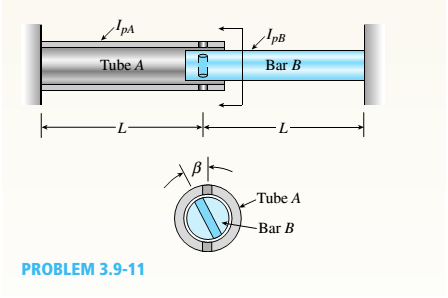
Chapter 3, Problem 3.9.11P
A hollow circular tube A fits over the end of a solid circular bar B, as shown in the figure. The far ends of both bars are fixed. Initially, a hole through bar B makes an angle ß with a line through two holes in tube A. Then bar B is twisted until the holes are aligned, and a pin is placed through the holes.
When bar B is released and the system returns to equilibrium, what is the total strain energy U of the two bars? (Let lAand lBrepresent the polar moments of inertia of bars A and B, respectively. The length L and shear modulus of elasticity G are the same for both bars.)
Expert Solution & Answer

Trending nowThis is a popular solution!

Chapter 3 Solutions
Mechanics of Materials (MindTap Course List)
Ch. 3 - A circular tube is subjected to torque Tat its...Ch. 3 - -2. A plastic bar of diameter d = 56 mm is to be...Ch. 3 - A copper rod of length L = 18.0 in. is to be...Ch. 3 - A circular steel tube of length L = 1.0 m is...Ch. 3 - Solve the preceding problem if the length L = 56...Ch. 3 - A circular aluminum tube subjected to pure torsion...Ch. 3 - A solid steel bar of circular cross section has...Ch. 3 - A solid copper bar of circular cross section has...Ch. 3 - Repeat Problem 3.3-1, but now use a circular tube...Ch. 3 - A copper tube with circular cross section has...
Ch. 3 - A prospector uses a hand-powered winch (see...Ch. 3 - When drilling a hole in a table leg, a furniture...Ch. 3 - While removing a wheel to change a tire, a driver...Ch. 3 - -8 An aluminum bar of solid circular cross section...Ch. 3 - A high-strength steel drill rod used for boring a...Ch. 3 - The steel shaft of a socket wrench has a diameter...Ch. 3 - A circular tube of aluminum is subjected to...Ch. 3 - A propeller shaft for a small yacht is made of a...Ch. 3 - Three identical circular disks A, B, and Care...Ch. 3 - The steel axle of a large winch on an ocean liner...Ch. 3 - A hollow steel shaft used in a construction auger...Ch. 3 - Solve the preceding problem if the shaft has an...Ch. 3 - A vertical pole of solid, circular cross section...Ch. 3 - A vertical pole of solid, circular cross section...Ch. 3 - A solid brass bar of diameter d = 1.25 in. is...Ch. 3 - A hollow aluminum tube used in a roof structure...Ch. 3 - A circular tube of inner radius r1and outer radius...Ch. 3 - .1 A stepped shaft ABC consisting of two solid...Ch. 3 - A circular tube of outer diameter d3= 70 mm and...Ch. 3 - A stepped shaft ABCD consisting of solid circular...Ch. 3 - A solid, circular bar ABC consists of two...Ch. 3 - A hollow tube ABCDE constructed of monel metal is...Ch. 3 - A shaft with a solid, circular cross section...Ch. 3 - Prob. 3.4.7PCh. 3 - Two sections of steel drill pipe, joined by bolted...Ch. 3 - Prob. 3.4.9PCh. 3 - -10. A tapered bar AB with a solid circular cross...Ch. 3 - A tapered bar AB with a solid circular cross...Ch. 3 - The bar shown in the figure is tapered linearly...Ch. 3 - The non prismatic, cantilever circular bar shown...Ch. 3 - A uniformly tapered tube AB with a hollow circular...Ch. 3 - A uniformly tapered aluminum-alloy tube AB with a...Ch. 3 - For the thin nonprismatic steel pipe of constant...Ch. 3 - .17 A mountain-bike rider going uphill applies...Ch. 3 - A prismatic bar AB of length L and solid circular...Ch. 3 - A prismatic bar AB with a solid circular cross...Ch. 3 - A magnesium-alloy wire of diameter d = 4mm and...Ch. 3 - A nonprismatic bar ABC with a solid circular cross...Ch. 3 - -22 Two tubes (AB, BC) of the same material arc...Ch. 3 - A circular copper bar with diameter d = 3 in. is...Ch. 3 - A circular steel tube with an outer diameter of 75...Ch. 3 - A hollow aluminum shaft (see figure) has an...Ch. 3 - A hollow steel bar (G = 80 GPa ) is twisted by...Ch. 3 - A tubular bar with outside diameterd2= 4.0 in, is...Ch. 3 - A solid circular bar of diameter d = 50 mm (see...Ch. 3 - -7 A steel tube (G = 11.5 x 10⁶ psi) has an outer...Ch. 3 - A solid circular bar of steel (G = 78 GPa)...Ch. 3 - The normal strain in the 45n direction on the...Ch. 3 - An aluminum tube has inside diameter dx= 50 mm,...Ch. 3 - -11 A solid steel bar (G = 11.8 X 10⁶ psi ) of...Ch. 3 - A solid aluminum bar (G = 27 GPa ) of diameter d =...Ch. 3 - Two circular aluminum pipes of equal length L = 24...Ch. 3 - A generator shaft in a small hydroelectric plant...Ch. 3 - A motor drives a shaft at 12 Hz and delivers 20 kW...Ch. 3 - A motor driving a solid circular steel shaft with...Ch. 3 - Prob. 3.7.4PCh. 3 - The propeller shaft of a large ship has an outside...Ch. 3 - The drive shaft for a truck (outer diameter 60 mm...Ch. 3 - A hollow circular shaft for use in a pumping...Ch. 3 - A tubular shaft being designed for use on a...Ch. 3 - A propeller shaft of solid circular cross section...Ch. 3 - What is the maximum power that can be delivered by...Ch. 3 - A motor delivers 275 hp at 1000 rpm to the end of...Ch. 3 - Prob. 3.7.12PCh. 3 - A solid circular bar ABCD with fixed supports is...Ch. 3 - A solid circular bar A BCD with fixed supports at...Ch. 3 - A solid circular shaft AB of diameter d is fixed...Ch. 3 - A ho 1 low st e el shaft ACB of outside diameter...Ch. 3 - A stepped shaft ACB having solid circular cross...Ch. 3 - A stepped shaft ACB having solid circular cross...Ch. 3 - A stepped shaft ACE is held against rotation at...Ch. 3 - A solid circulai' aluminum bar AB is fixed at both...Ch. 3 - Two sections of steel drill pipe, joined by bolted...Ch. 3 - A circular bar AB of length L is fixed against...Ch. 3 - A circular bar AB with ends fixed against rotation...Ch. 3 - A solid steel bar of diameter d1= 25.0 mm is...Ch. 3 - A solid steel bar of diameter d1= 1.50 in. is...Ch. 3 - The composite shaft shown in the figure is...Ch. 3 - The composite shaft shown in the figure is...Ch. 3 - A steel shaft (Gs= 80 GPa) of total length L = 3.0...Ch. 3 - A uniformly tapered aluminum-ally tube AB of...Ch. 3 - Two pipes {L, = 2.5 m and L, = 1.5 m) are joined...Ch. 3 - A solid circular bar of steel (G = 1L4 × 106 psi)...Ch. 3 - A solid circular bar of copper (G = 45 GPa) with...Ch. 3 - A stepped shaft of solid circular cross sections...Ch. 3 - A stepped shaft of solid circular cross sections...Ch. 3 - A circular tube AB is fixed at one end and free at...Ch. 3 - A cantilever bar of circular cross section and...Ch. 3 - Obtain a formula for the strain energy U of the...Ch. 3 - A statically indeterminate stepped shaft ACE is...Ch. 3 - Derive a formula for the strain energy U of the...Ch. 3 - A thin-walled hollow tube AB of conical shape has...Ch. 3 - A hollow circular tube A fits over the end of a...Ch. 3 - A heavy flywheel rotating at n revolutions per...Ch. 3 - A hollow circular tube having an inside diameter...Ch. 3 - A solid circular bar having diameter d is to be...Ch. 3 - A thin-walled aluminum tube of rectangular cross...Ch. 3 - A thin-walled steel tube of rectangular cross...Ch. 3 - A square tube section has side dimension of 20 in....Ch. 3 - A thin-walled circular tube and a solid circular...Ch. 3 - A thin-walled steel tube having an elliptical...Ch. 3 - Calculate the shear stress and the angle of twist...Ch. 3 - A torque T is applied to a thin-walled tube having...Ch. 3 - Compare the angle of twist 1 for a thin-walled...Ch. 3 - A tubular aluminum bar (G = 4 × 10⁶ psi) of square...Ch. 3 - A thin tubular shaft with a circular cross section...Ch. 3 - A thin-walled rectangular tube has uniform...Ch. 3 - A long, thin-walled tapered tube AB with a...Ch. 3 - A stepped shaft consisting of solid circular...Ch. 3 - A stepped shaft with diameters D1= 40 mm and D2=...Ch. 3 - A full quarter-circular fillet is used at the...Ch. 3 - The stepped shaft shown in the figure is required...Ch. 3 - A stepped shaft (see figure) has diameter D2= 1.5...
Knowledge Booster


Learn more about
Need a deep-dive on the concept behind this application? Look no further. Learn more about this topic, mechanical-engineering and related others by exploring similar questions and additional content below.Similar questions
- Two rigid bars are connected to each other by two linearly elastic springs. Before loads are applied, the lengths or the springs are such, that the bars are parallel and the springs are without stress. (a) Derive a formula for the displacement E4at point 4 when the load P is applied at joint 3 and moment PL is applied at joint 1. as shown in the figure part a. (Assume that the bars rotate through very small angles under the action of load P.) (b) Repeat part (a) if a rotational spring, kr= kL2, is now added at joint 6. What is the ratio of the deflection d4 in the figure part a to that in the figure part b ?arrow_forwardA polyethylene tube (length L) has a cap that when installed compresses a spring (with under-formed length L1) by an amount ?? = (L1 = L). Ignore deformations of the cap and base. Use the force at the base of the spring as the redundant. Use numerical properties given in the boxes. (a) What is the resulting Force-in the spring, Fk? (b) What is the resulting Force in the tube, Ftl (c) What is the filial length of the tube, Lf? (d) What temperature change ?T inside the tube will result in zero force in the springarrow_forwardThe L-shaped arm ABCD shown in the figure lies in a vertical plane and pivots about a horizontal pin at A. The arm has a constant cross-sectional area and total weight W. A vertical spring of stiffness k supports the arm at point B. (a) Obtain a formula for the elongation of the spring due to the weight of the arm. (b) Repeat part (a) if the pin support at A is moved to D.arrow_forward
- Solve the preceding problem if the cross- sectional dimensions are b = 1.5 in. and h = 5.0 in., the gage angle is ß = 750, the measured strains are = 209 × 10-6 and B = -110 × 10, and the material is a magnesium alloy with modulus E = 6.0 X 10⁶ psi and Poisson’s ratio v = 0.35.arrow_forwardA hollow circular pipe (see figure} support s a load P that is uniformly distributed around a cap plate at the top of the lower pipe. The inner and outer diameters of the upper and lower parts of the pipe are d1= 50 mm, d2= 60 mm, rf3 = 57 mm, and d1= 64 mm, respectively. Pipe lengths are Lt= 2 m and L, = 3 m. Neglect the self-weight of the pipes. Assume that cap plate thickness is small compared to I, and E,. Let E = 110 MPa. (a) If the tensile stress in the upper part is d = 10.5 MPa. what is load PI Also, what are reactions ft, at the upper support and R-, at the lower support? What is the stress ar(MPa) in the lower part? (b) Find displacement S(mm) at the cap plate. Plot the axial force diagram (AFD) [Ar(.f)] and axial displacement diagram (ADD)[5(.t)]. (c) Add the uniformly distributed load q along the censorial axis of pipe segment 2. Find q (kN/m) so that It, = 0. Assume that load P from part (a) is also applied.arrow_forwardA block B is pushed against three springs by a force P (see figure). The middle spring has a stillness K1and the outer springs each have stiffness k^. Initially, the springs are unstressed, and the middle spring is longer than the outer springs (the difference in length is denoted s). (a) Draw a force-displacement diagram with the force P as ordinate and the displacement x of the block as abscissa. (b) From the diagram, determine the strain energy U1 of the springs when x = 2s. (c) Explain why the strain energy E, is not equal to Parrow_forward
- The normal strain in the 45n direction on the surface of a circular tube (sec figure) is 880 × 10 when the torque T = 750 lb-in. The tube is made of copper alloy with G = 6.2 × 10⁶ psi and y = 0.35. If the outside diameter d2of the tube is 0.8 in., what is the inside diameter dt? If the allowable normal stress in the tube is 14 ksi, what is the maximum permissible inside diameter d?arrow_forward-11 A solid steel bar (G = 11.8 X 10⁶ psi ) of diameter d = 2,0 in. is subjected to torques T = 8.0 kip-in. acting in the directions shown in the figure. Determine the maximum shear, tensile, and compressive stresses in the bar and show these stresses on sketches of properly oriented stress elements. Determine the corresponding maximum strains (shear, tensile, and compressive) in the bar and show these strains on sketches of the deformed elements.arrow_forwardA uniformly tapered lube AB of circular cross section and length L is shown in the figure. The average diameters at the ends are dAand d£= 2d t. Assume E is constant. Find the elongation S of the tube when it is subjected to loads P acting at the ends. Use the following numerical data:^ = 35 mm, L = WO mm, E = 2.1 GPa. and P = 25 tN. Consider the following cases. (a) A hole of constant diameter dAis drilled from B toward A to form a hollow section of length x - U2. (b) A hole of variable diameter a\.x) is drilled, from B toward A to form a hollow section of length x = L/2 and constant thickness t = dA/20.arrow_forward
- A circular bar ACB of a diameter d having a cylindrical hole of length .r and diameter till from A to C is held between rigid supports at A and B. A load P acts at U2from ends A and B. Assume E is constant. (a) Obtain formulas for the reactions R, and RBat supports A and B. respectively, due to the load P (see figure part a). (b) Obtain a formula for the displacement S at the point of load application (see figure part a). (c) For what value of x is RB= (6/5)?,? (See figure part a.) (d) Repeat part (a) if the bar is now rotated to a vertical position, load P is removed, and the bar is hanging under its own weight (assume mass density = p). (See figure part b.) Assume that x = LI2.arrow_forwardA circular aluminum tube of length L = 600 mm is loaded in compression by forces P (see figure). The outside and inside diameters are d2= 75 mm and d1= 63 mm, respectively. A strain gage is placed on the outside of the lube to measure normal strains in the longitudinal direction. Assume that E = 73 GPa and Poissons ratio is v = 0.33. (a) IF the compressive stress in the tube is 57 MPa, what is the load P? (b) If the measured strain is e = 78 J X 10-6, what is the shorteningarrow_forwardA brass cube of 48 mm on each edge is comp ressed in two perpendicular directions by forces P = 160 kN (see figure). (a) Calculate the change ...IV in the volume of the cube and the strain energy U stored in the cube. assuming E = 100 GPa and i’ = 0.34. (b) Repeat part (a) if the cube is made of an alumim um alloy with E = 73 GPa and v = 0.33.arrow_forward
arrow_back_ios
SEE MORE QUESTIONS
arrow_forward_ios
Recommended textbooks for you
 Mechanics of Materials (MindTap Course List)Mechanical EngineeringISBN:9781337093347Author:Barry J. Goodno, James M. GerePublisher:Cengage Learning
Mechanics of Materials (MindTap Course List)
Mechanical Engineering
ISBN:9781337093347
Author:Barry J. Goodno, James M. Gere
Publisher:Cengage Learning
Strain energy and strain energy density introduced; Author: Engineer4Free;https://www.youtube.com/watch?v=m14sqLGg4BQ;License: Standard youtube license