
Fundamentals of Electric Circuits
6th Edition
ISBN: 9780078028229
Author: Charles K Alexander, Matthew Sadiku
Publisher: McGraw-Hill Education
expand_more
expand_more
format_list_bulleted
Concept explainers
Videos
Textbook Question
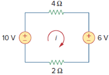
Chapter 3, Problem 5RQ
The circuit i in the circuit of Fig. 3.48 is:
(a) −2.667 A
(b) −0.667 A
(c) 0.667 A
(d) 2.667 A
Expert Solution & Answer
Want to see the full answer?
Check out a sample textbook solution
Students have asked these similar questions
16. Determine the Equivalent Resistance R, for the circuit below.
3502
1002
4002
2002
12V
5002
3002
2502
502
1502
For the following electrical circuit in R3 = 649ohm determine by the method of Superposition theorem: the electric current, Voltage and Power dissipated in the circuit
Q3: find the current through the 48ohm resistor in the circuit and assume the diode is silicon diode and
the forward internal resistor of the diode is 1ohm.
10 V
D₁
D4
(i)
48 Ω
ww
D2
D3
Chapter 3 Solutions
Fundamentals of Electric Circuits
Ch. 3.2 - Figure 3.4 For Practice Prob. 3.1. Obtain the node...Ch. 3.2 - Figure 3.6 For Practice Prob. 3.2. Find the...Ch. 3.3 - Figure 3.11 For Practice Prob. 3.3. Find v and i...Ch. 3.3 - Figure 3.14 For Practice Prob. 3.4. Find v1, v2,...Ch. 3.4 - Practice Problem 3.5 Figure 3.19 For Practice...Ch. 3.4 - Practice Problem 3.6 Figure 3.21 For Practice...Ch. 3.5 - Practice Problem 3.7 Figure 3.25 For Practice...Ch. 3.6 - By inspection, obtain the node-voltage equations...Ch. 3.6 - By inspection, obtain the mesh-current equations...Ch. 3.8 - For the circuit in Fig. 3.33, use PSpice to find...
Ch. 3.8 - Use PSpice to determine currents i1, i2, and i3 in...Ch. 3.9 - For the transistor circuit in Fig. 3.42, let =...Ch. 3.9 - The transistor circuit in Fig. 3.45 has = 80 and...Ch. 3 - At node 1 in the circuit of Fig. 3.46, applying...Ch. 3 - Figure 3.46 For Review Questions 3.1 and 3.2 In...Ch. 3 - For the circuit in Fig. 3.47, v1 and v2 are...Ch. 3 - Figure 3.47 For Review Questions 3.3 and 3.4....Ch. 3 - The circuit i in the circuit of Fig. 3.48 is:...Ch. 3 - Figure 3.48 For Review Questions 3.5 and 3.6....Ch. 3 - In the circuit of Fig. 3.49, current i1 is: (a)4 A...Ch. 3 - Figure 3.49 For Review Questions 3.7 and 3.8....Ch. 3 - The PSpice part name for a current-controlled...Ch. 3 - Which of the following statements are not true of...Ch. 3 - Using Fig. 3.50, design a problem to help other...Ch. 3 - For the circuit in Fig. 3.51, obtain v1 and v2....Ch. 3 - Find the currents I1 through I4 and the voltage vo...Ch. 3 - Given the circuit in Fig. 3.53, calculate the...Ch. 3 - Obtain vo in the circuit of Fig. 3.54. Figure 3.54...Ch. 3 - Solve for V1 in the circuit of Fig. 3.55 using...Ch. 3 - Apply nodal analysis to solve for Vx in the...Ch. 3 - Using nodal analysis, find vo in the circuit of...Ch. 3 - Determine Ib in the circuit in Fig. 3.58 using...Ch. 3 - Prob. 10PCh. 3 - Find Vo and the power dissipated in all the...Ch. 3 - Using nodal analysis, determine Vo in the circuit...Ch. 3 - Calculate v1 and v2 in the circuit of Fig. 3.62...Ch. 3 - Using nodal analysis, find vo in the circuit of...Ch. 3 - Apply nodal analysis to find io and the power...Ch. 3 - Determine voltages v1 through v3 in the circuit of...Ch. 3 - Prob. 17PCh. 3 - Determine the node voltages in the circuit in Fig....Ch. 3 - Use nodal analysis to find v1, v2 and v3 in the...Ch. 3 - For the circuit in Fig. 3.69, find v1, v2, and v3...Ch. 3 - For the circuit in Fig. 3.70, find v1 and v2 using...Ch. 3 - Determine v1 and v2 in the circuit of Fig. 3.71....Ch. 3 - Use nodal analysis to find Vo in the circuit of...Ch. 3 - Use nodal analysis and MATLAB to find Vo in the...Ch. 3 - Use nodal analysis along with MATLAB to determine...Ch. 3 - Calculate the node voltages v1, v2, and v3 in the...Ch. 3 - Use nodal analysis to determine voltages v1, v2,...Ch. 3 - Use MATLAB to find the voltages at nodes a, b, c,...Ch. 3 - Use MATLAB to solve for the node voltages in the...Ch. 3 - Using nodal analysis, find vo and io in the...Ch. 3 - Find the node voltages for the circuit in Fig....Ch. 3 - Obtain the node voltages v1, v2, and v3 in the...Ch. 3 - Which of the circuits in Fig. 3.82 is planar? For...Ch. 3 - Determine which of the circuits in Fig. 3.83 is...Ch. 3 - Figure 3.54 For Prob. 3.5. Rework Prob. 3.5 using...Ch. 3 - Use mesh analysis to obtain ia, ib, and ic in the...Ch. 3 - Using nodal analysis, find vo in the circuit of...Ch. 3 - Apply mesh analysis to the circuit in Fig. 3.85...Ch. 3 - Using Fig. 3.50 from Prob. 3.1, design a problem...Ch. 3 - Prob. 40PCh. 3 - Apply mesh analysis to find i in Fig. 3.87. Figure...Ch. 3 - Using Fig. 3.88, design a problem to help students...Ch. 3 - Prob. 43PCh. 3 - Prob. 44PCh. 3 - Prob. 45PCh. 3 - Calculate the mesh currents i1 and i2 in Fig....Ch. 3 - Rework Prob. 3.19 using mesh analysis. Use nodal...Ch. 3 - Prob. 48PCh. 3 - Find vo and io in the circuit of Fig. 3.94. Figure...Ch. 3 - Prob. 50PCh. 3 - Apply mesh analysis to find vo in the circuit of...Ch. 3 - Use mesh analysis to find i1, i2 and i3 in the...Ch. 3 - Prob. 53PCh. 3 - Find the mesh currents i1, i2, and i3 in the...Ch. 3 - In the circuit of Fig. 3.100, solve for I1, I2,...Ch. 3 - Determine v1 and v2 in the circuit of Fig. 3.101....Ch. 3 - In the circuit of Fig. 3.102, find the values of...Ch. 3 - Find i1, i2, and i3 in the circuit of Fig. 3.103....Ch. 3 - Rework Prob. 3.30 using mesh analysis. Using nodal...Ch. 3 - Prob. 60PCh. 3 - Calculate the current gain iois in the circuit of...Ch. 3 - Find the mesh currents i1, i2, and i3 in the...Ch. 3 - Find vx and ix in the circuit shown in Fig. 3.107....Ch. 3 - Find vo and io in the circuit of Fig. 3.108.Ch. 3 - Use MATLAB to solve for the mesh currents in the...Ch. 3 - Write a set of mesh equations for the circuit in...Ch. 3 - Obtain the node-voltage equations for the circuit...Ch. 3 - Prob. 68PCh. 3 - For the circuit shown in Fig. 3.113, write the...Ch. 3 - Write the node-voltage equations by inspection and...Ch. 3 - Write the mesh-current equations for the circuit...Ch. 3 - Prob. 72PCh. 3 - Write the mesh-current equations for the circuit...Ch. 3 - By inspection, obtain the mesh-current equations...Ch. 3 - Use PSpice or MultiSim to solve Prob. 3.58....Ch. 3 - Use PSpice or MultiSim to solve Prob. 3.27....Ch. 3 - Solve for V1 and V2 in the circuit of Fig. 3.119...Ch. 3 - Solve Prob. 3.20 using PSpice or MultiSim. 3.20...Ch. 3 - Prob. 79PCh. 3 - Find the nodal voltages v1 through v4 in the...Ch. 3 - Use PSpice or MultiSim to solve the problem in...Ch. 3 - If the Schematics Netlist for a network is as...Ch. 3 - The following program is the Schematics Netlist of...Ch. 3 - Prob. 84PCh. 3 - An audio amplifier with a resistance of 9 ...Ch. 3 - Prob. 86PCh. 3 - For the circuit in Fig. 3.123, find the gain...Ch. 3 - Determine the gain vo/vs of the transistor...Ch. 3 - For the transistor circuit shown in Fig. 3.125,...Ch. 3 - Calculate vs for the transistor in Fig. 3.126...Ch. 3 - Prob. 91PCh. 3 - Prob. 92PCh. 3 - Rework Example 3.11 with hand calculation. In the...
Knowledge Booster


Learn more about
Need a deep-dive on the concept behind this application? Look no further. Learn more about this topic, electrical-engineering and related others by exploring similar questions and additional content below.Similar questions
- The subject is: Smart Grid Applications and Technologies Q2arrow_forward7. With the help of circuit diagram (Fig3) given below draw the output voltage and current waveform D₂ S Figure 3: circuit diagram KH D₂arrow_forwardQ1) Find the time constants for the circuits shown below. a) C2 R3 5ko R1 10ka R2 10ka R4 10ka 0.2uF C1 =0.1µF C3 0.33pF b) R1 5kQ L1 50mH R2 R3 L2 33mH 5kQ R4 5kQarrow_forward
- A certain current source has the values IS = 4 µA and RS = 1.2 MO. The values for an equivalent voltage sourcearrow_forwardQ3: Simplify the following circuit, and draw the simplified circuit? D F• X N.arrow_forwardQ3/B: Determine i, for t> 0 for the circuit shown below IkN ww Ikn +0.25 mF 30 mA 2k2 wwarrow_forward
- solve using superposition.arrow_forwardThe text is red is what needs to be solved. The other picture is providing the circuit that is in question. Thank you!arrow_forwardFor the circuit shown below, Determine the power dissipated in R5 R Ry R 20 40 9 V R10 R sn 7A Select one: a. 21 W b. 70 W c. 147 W d. 63 Warrow_forward
- Q2/ Find the state-space representation of the electrical network shown in Figure 3.8. The output is vo(t). C₁ im V (1) ellearrow_forwardBasics of Electrical Engineering Assignment 1 Use Thevenin's Theorem to show that the current I in the R3 = 200 N resistance in the circuit shown below equals 300 m amp: R1 R2 750 1500 V1 R3 2000 V2 -80V 140V R5 R4 1250 2500arrow_forwardFor the value of RL for which the maximum power will be delivered to the load. Also, find the value of maximum power that is delivered to the load. * R1 RL 802 5V I 0.5A R23402 3V 402 602 R4arrow_forward
arrow_back_ios
SEE MORE QUESTIONS
arrow_forward_ios
Recommended textbooks for you
 Introductory Circuit Analysis (13th Edition)Electrical EngineeringISBN:9780133923605Author:Robert L. BoylestadPublisher:PEARSON
 Delmar's Standard Textbook Of ElectricityElectrical EngineeringISBN:9781337900348Author:Stephen L. HermanPublisher:Cengage Learning
 Programmable Logic ControllersElectrical EngineeringISBN:9780073373843Author:Frank D. PetruzellaPublisher:McGraw-Hill Education
 Fundamentals of Electric CircuitsElectrical EngineeringISBN:9780078028229Author:Charles K Alexander, Matthew SadikuPublisher:McGraw-Hill Education
 Electric Circuits. (11th Edition)Electrical EngineeringISBN:9780134746968Author:James W. Nilsson, Susan RiedelPublisher:PEARSON
 Engineering ElectromagneticsElectrical EngineeringISBN:9780078028151Author:Hayt, William H. (william Hart), Jr, BUCK, John A.Publisher:Mcgraw-hill Education,
Introductory Circuit Analysis (13th Edition)
Electrical Engineering
ISBN:9780133923605
Author:Robert L. Boylestad
Publisher:PEARSON
Delmar's Standard Textbook Of Electricity
Electrical Engineering
ISBN:9781337900348
Author:Stephen L. Herman
Publisher:Cengage Learning
Programmable Logic Controllers
Electrical Engineering
ISBN:9780073373843
Author:Frank D. Petruzella
Publisher:McGraw-Hill Education
Fundamentals of Electric Circuits
Electrical Engineering
ISBN:9780078028229
Author:Charles K Alexander, Matthew Sadiku
Publisher:McGraw-Hill Education
Electric Circuits. (11th Edition)
Electrical Engineering
ISBN:9780134746968
Author:James W. Nilsson, Susan Riedel
Publisher:PEARSON
Engineering Electromagnetics
Electrical Engineering
ISBN:9780078028151
Author:Hayt, William H. (william Hart), Jr, BUCK, John A.
Publisher:Mcgraw-hill Education,
Thevenin's Theorem; Author: Neso Academy;https://www.youtube.com/watch?v=veAFVTIpKyM;License: Standard YouTube License, CC-BY