
Videos
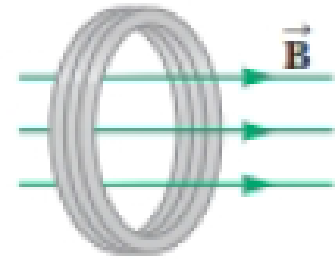
Figure P30.41 shows a compact, circular coil with 220 turns and radius 12.0 cm immersed in a uniform magnetic field parallel to the axis of the coil. The rate of change of the field has the constant magnitude 20.0 mT/s. (a) What additional information is necessary to determine whether the coil is carrying clockwise or counterclockwise current? (b) The coil overheats if more than 160 W of power is delivered to it. What resistance would the coil have at this critical point? (c) To run cooler, should it have lower resistance or higher resistance?
Figure P30.41

Trending nowThis is a popular solution!

Chapter 30 Solutions
Physics for Scientists and Engineers with Modern Physics
Additional Science Textbook Solutions
Matter and Interactions
Physics: Principles with Applications
Loose Leaf For Explorations: Introduction To Astronomy
The Physical Universe
College Physics: A Strategic Approach (3rd Edition)


- Consider the apparatus shown in Figure P30.32: a conducting bar is moved along two rails connected to an incandescent lightbulb. The whole system is immersed in a magnetic field of magnitude B = 0.400 T perpendicular and into the page. The distance between the horizontal rails is = 0.800 m. The resistance of the lightbulb is R = 48.0 , assumed to be constant. The bar and rails have negligible resistance. The bar is moved toward the right by a constant force of magnitude F = 0.600 N. We wish to find the maximum power delivered to the lightbulb. (a) Find an expression for the current in the lightbulb as a function of B, , R, and v, the speed of the bar. (b) When the maximum power is delivered to the lightbulb, what analysis model properly describes the moving bar? (c) Use the analysis model in part (b) to find a numerical value for the speed v of the bar when the maximum power is being delivered to the lightbulb. (d) Find the current in the lightbulb when maximum power is being delivered to it. (e) Using P = I2R, what is the maximum power delivered to the lightbulb? (f) What is the maximum mechanical input power delivered to the bar by the force F? (g) We have assumed the resistance of the lightbulb is constant. In reality, as the power delivered to the lightbulb increases, the filament temperature increases and the resistance increases. Does the speed found in part (c) change if the resistance increases and all other quantities are held constant? (h) If so, does the speed found in part (c) increase or decrease? If not, explain. (i) With the assumption that the resistance of the lightbulb increases as the current increases, does the power found in part (f) change? (j) If so, is the power found in part (f) larger or smaller? If not, explain. Figure P30.32arrow_forwardA circular loop of wire with a radius of 4.0 cm is in a uniform magnetic field of magnitude 0.060 T. The plane of the loop is perpendicular to the direction of the magnetic field. In a time interval of 0.50 s, the magnetic field changes to the opposite direction with a magnitude of 0.040 T. What is the magnitude of the average emf induced in the loop? (a) 0.20 V (b) 0.025 V (c) 5.0 mV (d) 1.0 mV (e) 0.20 mVarrow_forwardA Figure P32.74 shows an N-turn rectangular coil of length a and width b entering a region of uniform magnetic field of magnitude Bout directed out of the page. The velocity of the coil is constant and is upward in the figure. The total resistance of the coil is R. What are the magnitude and direction of the magnetic force on the coil a. when only a portion of the coil has entered the region with the field, b. when the coil is completely embedded in the field, and c. as the coil begins to exit the region with the field?arrow_forward
- A conducting rod of length = 35.0 cm is free to slide on two parallel conducting bars as shown in Figure P30.35. Two resistors R1 = 2.00 and R2 = 5.00 are connected across the ends of the bars to form a loop. A constant magnetic field B = 2.50 T is directed perpendicularly into the page. An external agent pulls the rod to the left with a constant speed of v = 8.00 m/s. Find (a) the currents in both resistors, (b) the total power delivered to the resistance of the circuit, and (c) the magnitude of the applied force that is needed to move the rod with this constant velocity. Figure P30.35arrow_forwardA flat, square coil of 20 turns that has sides of length 15.0 cm is rotating in a magnetic field of strength 0.050 T. If tlie maximum emf produced in die coil is 30.0 mV, what is the angular velocity of the coil?arrow_forwardA constant magnetic field of 0.275 T points through a circular loop of wire with radius 3.50 cm as shown in Figure P32.1. a. What is the magnetic flux through the loop? b. Is a current induced in the loop? Explain. FIGURE P32.1arrow_forward
- The square armature coil of an alternating current generator has 200 turns and is 20.0 cm on side. When it rotates at 3600 rpm, its peak output voltage is 120 V. (a) Wliat is the frequency' of the output voltage? (b) What is the strength of the magnetic field in which the coil is turning?arrow_forwardA piece of insulated wire is shaped into a figure eight as shown in Figure P23.12. For simplicity, model the two halves of the figure eight as circles. The radius of the upper circle is 5.00 cm and that of the lower circle is 9.00 cm. The wire has a uniform resistance per unit length of 3.00 Ω/m. A uniform magnetic field is applied perpendicular to the plane of the two circles, in the direction shown. The magnetic field is increasing at a constant rate of 2.00 T/s. Find (a) the magnitude and (b) the direction of the induced current in the wire. Figure P23.12arrow_forwardA circular loop of wire of resistance R = 0.500 and radius r = 8.00 cm is in a uniform magnetic field directed out of the page as in Figure P31.54. If a clockwise current of I = 2.50 mA is induced in the loop, (a) is the magnetic field increasing or decreasing in time? (b) Find the rate at which the field is changing with time. Figure P31.54arrow_forward
- A square loop whose sides are 6.0-cm long is made with copper wire of radius 1.0 mm. If a magnetic field perpendicular to the loop is changing at a rate of 5.0 mT/s, what is the current in the loop?arrow_forwardA coil with a self-inductance of 3.0 H and a resistance of 100 2 carries a steady current of 2.0 A. (a) What is the energy stored in the magnetic field of the coil? (b) What is the energy per second dissipated in the resistance of the coil?arrow_forwardWhy is the following situation impossible? A conducting rectangular loop of mass M = 0.100 kg, resistance R = 1.00 , and dimensions w = 50.0 cm by = 90.0 cm is held with its lower edge just above a region with a uniform magnetic field of magnitude B = 1.00 T as shown in Figure P30.34. The loop is released from rest. Just as the top edge of the loop reaches the region containing the field, the loop moves with a speed 4.00 m/s. Figure P30.34arrow_forward
 Physics for Scientists and Engineers: Foundations...PhysicsISBN:9781133939146Author:Katz, Debora M.Publisher:Cengage Learning
 Physics for Scientists and Engineers, Technology ...PhysicsISBN:9781305116399Author:Raymond A. Serway, John W. JewettPublisher:Cengage Learning
 Principles of Physics: A Calculus-Based TextPhysicsISBN:9781133104261Author:Raymond A. Serway, John W. JewettPublisher:Cengage Learning
 Physics for Scientists and Engineers with Modern ...PhysicsISBN:9781337553292Author:Raymond A. Serway, John W. JewettPublisher:Cengage Learning
 Physics for Scientists and EngineersPhysicsISBN:9781337553278Author:Raymond A. Serway, John W. JewettPublisher:Cengage Learning