Videos
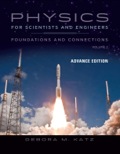
Three long, current-carrying wires are parallel to one another and separated by a distance d. The magnitudes and directions of the currents are shown in Figure P30.91. Wires 1 and 3 are fixed, but wire 2 is free to move. Wire 2 is displaced to the right by a small distance x. Determine the net force (per unit length) acting on wire 2 and the angular frequency of the resulting oscillation. Assume the mass per unit length of wire 2 is λ and x ≪ d.
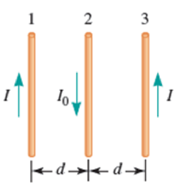
FIGURE P30.91
(a)
The net force per unit length acting on wire
Answer to Problem 91PQ
The net force (per unit length) acting on wire
Explanation of Solution
The wire
The direction of magnetic field on wire
Write the expression of the force between two parallel current carrying conductors per unit length.
Here,
Substitute
Here,
Substitute
Here,
Write the expression for the net force on wire
Conclusion:
Substitute
Since
This implies that
Thus, the net force (per unit length) acting on wire
(b)
The angular frequency of the resulting oscillation.
Answer to Problem 91PQ
The angular frequency of the resulting oscillating is
Explanation of Solution
Rewrite the equation (V).
Since, the wire
Write the expression for the force experienced by the wire
Rearrange the above expression.
Here,
Substitute
Rearrange the above expression.
Write the general expression for our oscillating wave.
Here,
Compare equation (VIII) is and (IX) for the coefficient of
Conclusion:
Hence, the angular frequency of the resulting oscillation is
Want to see more full solutions like this?
Chapter 30 Solutions
EBK PHYSICS FOR SCIENTISTS AND ENGINEER


- A conducting loop in Figure Q2(b) moves at a constant velocity, u = f10 m/s away from a long straight wire carrying current of 12 A. If resistances R = 50 2, determine the current I2. Please take note that the direction of Iz is as defined in the figure. R I =12 A 8 cm R 10 cm 6 cmarrow_forwardDerive an expression for the current in a system like shown, under the following conditions. The resistance between the rails is R , the rails and the moving rod are identical in cross section A and have the same resistivity ρ .The distance between the rails is l, and the rod moves at constant speed v perpendicular to the uniform field B . At time zero, the moving rod is next to the resistance R .arrow_forwardPr1. The figure shows the cross-section of a long, straight, cylindrical coil (solenoid) of radius r = 10 cm. The number of turns per unit length is n = 500 m-1. A direct current I = 1,0 A flows clockwise in the solenoid. A charged particle accelerated by a voltage 1000 V enters into the solenoid through a gap between the coils at point A. The velocity of the particle at point A is pointing along the radius. The particle is traveling inside the solenoid in a plane perpendicular to its axis and exits at point C at an angle a = 60° to its initial direction. 60 Av a) Determine the sign of the charge of the particle. b) What is the radius of the particle's trajectory? c) Find the charge-to-mass (Q/m) ratio of the particle. (The magnetic permeability of vacuum is µo = 47 - 10-7 Vs/Am.)arrow_forward
- A thin wire ℓ = 30.0 cm long is held parallel to and d = 80.0 cm above a long, thin wire carrying I = 200 A and fixed in position (Fig. P30.47). The 30.0-cm wire is released at the instant t = 0 and falls, remaining parallel to the current-carrying wire as it falls. Assume the falling wire accelerates at 9.80 m/s2. (a) Derive an equation for the emf induced in it as a function of time. (b) What is the minimum value of the emf? (c) What is the maximum value? (d) What is the induced emf 0.300 s after the wire is released?arrow_forwardYou are working during the summer at a company that builds theme parks. The company is designing an electromagnetic propulsion system for a new roller coaster. A model of a substructure of the device appears in the figure below. B L The rod is of length d = 1.00 m and mass m = 0.600 kg. The rod carries a current I = 100 A in the direction shown and rolls along the rails of length L = 15.0 m without slipping. The entire system of rod and rails is immersed in a uniform downward-directed magnetic field with magnitude B = 2.00 T. The electromagnetic force on the rod is parallel to the rails, causing the rod to roll to the right in the figure. When a full-scale device is produced, this rod will represent the axle of wheels on which the car and its passengers ride. The electromagnetic force on the axle will provide the motion of the car at the beginning of the roller-coaster ride. Your supervisor wants to test the substructure in the figure in a flat outdoor area on the grounds of the…arrow_forwardSuppose you have a long straight wire AB, carrying a current in the direction shown in the figure. Below this wire is a rectangular loop 20 cm long and 5 cm wide, carrying a current of equal magnitude to the wire, where the long sides are parallel to the wire. The wire and the loop both have a linear density equal to 0.0125 kg/m. The separation between the upper long side of the loop and the wire is 1 cm. What would happen if you move the loop just a little bit down?arrow_forward
- The figure at right shows the top view of a bar that can slide on two parallel rails without friction. A constant external force Fapp is applied to the bar causing it to slide to the right. A uniform magnetic field B is directed into the page. R (a.) If the applied force causes the bar to slide with a constant velocity v = 2 m/s, what is the direction and magnitude of the current through the resistor? Take B= 0.5 T l = 10 cm, and R = 20 2. Solve the problem algebraically first, then plug in numbers. (b.) | Find the magnitude and direction of the magnetic force on the rod due to this motion. (If you do not solve part (a), give an algebraic answer in terms of well-identified quantities for partial credit.)arrow_forwardA rectangular loop of wire with sides H = 27 cm and W = 64 cm carries current I2 = 0.352 A. An infinite straight wire, located a distance L = 31 cm from segment ad of the loop as shown, carries current I1 = 0.58 A in the positive y-direction. W I, 1" What is Fadx, the x-component of the force exerted by the infinite wire on segment ad of the loop? N Submit 2) What is Fhc x, the x-component of the force exerted by the infinite wire on segment bc of the loop?. N Submit 3) What is Fnet,y, the y-component of the net force exerted by the infinite wire on the loop? N Submit 4) Another infinite straight wire, aligned with the y-axis is now added at a distance 2L = 62 cm from segment bc of the loop as shown. A current, I3, flows in this wire. The loop now experiences a net force of zero. 2L Ay What is the direction of I3? O along the positive y-direction O along the negative y-direction Submit 5) What is the magnitude of I3? A Submitarrow_forwardA 40 cm long copper wire carries a current of 6 A and weighs 0.35 N. A certain magnetic field is strong enough to balance the force of gravity on the wire. What is the strength of the magnetic field in Teslas(T). Hint recall F(magnetic Field) = I x L x B, where I is current, L is length of the wire and B is the magnetic field.arrow_forward
- A the moving rod has a resistance of 0.25 Ω and moves on rails 20.0 cm apart. The stationary U-shaped conductor has negligible resistance. When a force of 0.410 N is applied to the rod, it moves to the right at a constant speed of 1.50 m/s. What is the magnetic field?arrow_forwardConsider a 150 turn square loop of wire 16 cm on a side that carries a 56 A current in a 1.75 T field. l = 16 cmI = 56 AB = 1.75 T a. What is the maximum torque on the loop of wire in N⋅m? b. What is the magnitude of the torque in N⋅m when the angle between the field and the normal to the plane of the loop θ is 14°?arrow_forwardA student performs an experiment to study the magnetic force on a current carrying wire placed in an external magnetic field. The magnetic field is uniform. A wire is placed making an angle 0 with the magnetic field lines. The student keeps the magnetic field, the current flowing in the wire and the length of the wire fixed. She measures the force on the wire for different values of 0. She wants to plot F versus some function of 0, such that she can obtain a linear graph. What function of 0 should she use? Select one: O cot(0) cos(0) sin(0) O tan(0)arrow_forward
 Physics for Scientists and Engineers: Foundations...PhysicsISBN:9781133939146Author:Katz, Debora M.Publisher:Cengage Learning