
Videos
(a)
The phasor diagram if the capacitance is
(a)
Answer to Problem 66PQ
The phasor diagram of the circuit is shown below.
Explanation of Solution
Write the expression for the impedance.
Here,
Write the expression to calculate the inductive reactance.
Here,
Write the expression for the capacitive reactance.
Here,
Substitute the
Write the expression for maximum current in the circuit.
Here,
Write the expression for phase angle.
Conclusion:
Substitute
Substitute
Substitute
The phase angle is
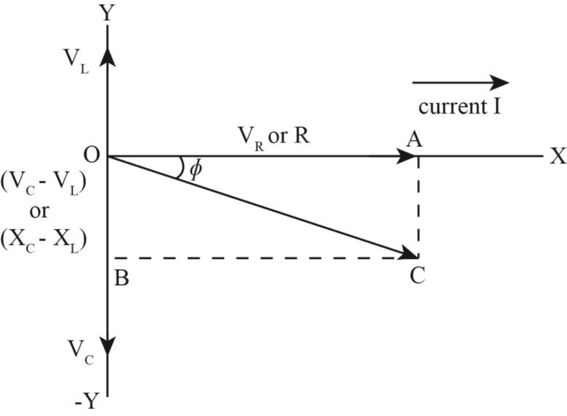
The inductive reactance is less than the capacitive reactance. Hence, the phasor angle is negative.
The phasor diagram of the circuit is shown below. 
Figure (1)
(b)
The phasor diagram if the capacitance is
(b)
Answer to Problem 66PQ
The phasor diagram of the circuit is shown below.
Explanation of Solution
Write the expression for the impedance.
Here,
Write the expression to calculate the inductive reactance.
Here,
Write the expression for the capacitive reactance.
Here,
Substitute the
Write the expression for maximum current in the circuit.
Here,
Write the expression for phase angle.
Conclusion:
Substitute
Substitute
Substitute
The phase angle is
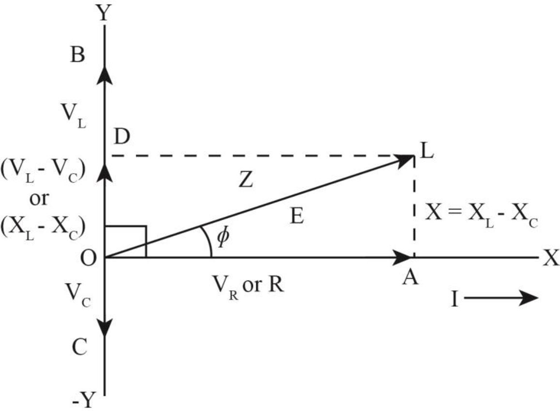
The inductive reactance is less than the capacitive reactance. Hence, the phasor angle is negative.
The phasor diagram of the circuit is shown below.

Want to see more full solutions like this?
Chapter 33 Solutions
Physics for Scientists and Engineers: Foundations and Connections


 College PhysicsPhysicsISBN:9781305952300Author:Raymond A. Serway, Chris VuillePublisher:Cengage Learning
 University Physics (14th Edition)PhysicsISBN:9780133969290Author:Hugh D. Young, Roger A. FreedmanPublisher:PEARSON
 Introduction To Quantum MechanicsPhysicsISBN:9781107189638Author:Griffiths, David J., Schroeter, Darrell F.Publisher:Cambridge University Press
 Physics for Scientists and EngineersPhysicsISBN:9781337553278Author:Raymond A. Serway, John W. JewettPublisher:Cengage Learning
 Lecture- Tutorials for Introductory AstronomyPhysicsISBN:9780321820464Author:Edward E. Prather, Tim P. Slater, Jeff P. Adams, Gina BrissendenPublisher:Addison-Wesley
 College Physics: A Strategic Approach (4th Editio...PhysicsISBN:9780134609034Author:Randall D. Knight (Professor Emeritus), Brian Jones, Stuart FieldPublisher:PEARSON