Videos
(a)
The current in the circuit as a function of time.
(a)
Answer to Problem 72AP
The current in the circuit as a function of time is
Explanation of Solution
The circuit in which capacitor and inductor are short circuited and both the switch are closed is as shown below.
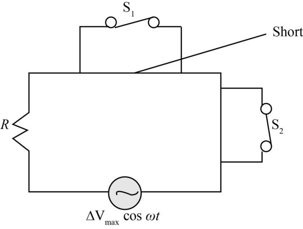
Figure-(1)
Write the expression to obtain the time varying voltage source.
Here,
Write the expression to obtain the current in the circuit as a function of time.
Here,
Substitute
Conclusion:
Therefore, the current in the circuit as a function of time is
(b)
The power delivered to the circuit.
(b)
Answer to Problem 72AP
The power delivered to the circuit is
Explanation of Solution
Write the expression to obtain the power delivered to the circuit.
Here,
Substitute
Conclusion:
Therefore, the power delivered to the circuit is
(c)
The current in the circuit as function of time if only switch
(c)
Answer to Problem 72AP
The current in the circuit as function of time if only switch
Explanation of Solution
The circuit in which switch
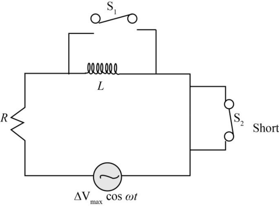
Figure-(2)
In case of inductor circuit, the phase difference between the current and voltage is
Write the expression to obtain the time varying voltage source in case
Here,
Write the expression to obtain the impedance in the circuit.
Here,
Write the expression to obtain the current in the circuit as a function of time.
Here,
Substitute
Conclusion:
Therefore, the current in the circuit as function of time if only switch
(d)
The capacitance of the capacitor when both the switches are closed and the current and voltage are in phase.
(d)
Answer to Problem 72AP
The capacitance of the capacitor when both the switches are open and the current and voltage are in phase is
Explanation of Solution
The circuit in which both the switches are open as shown in the figure below.
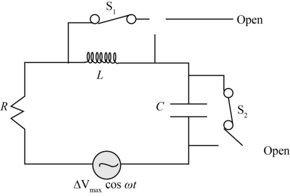
Figure-(3)
Write the expression obtain the impendence of the inductor.
Here,
Write the expression obtain the impendence of the capacitor.
Here,
When the current and voltage in the circuit are in phase, than the impendence of the inductor and the capacitor are equal.
Write the expression to obtain the relation the capacitance of the capacitor.
Here,
Substitute
Conclusion:
Therefore, the capacitance of the capacitor when both the switches are open and the current and voltage are in phase is
(e)
The impendence of the circuit when both the switches are open.
(e)
Answer to Problem 72AP
The impendence of the circuit when both the switches are open is
Explanation of Solution
Write the expression when both the switches are open.
Here,
Write the expression to obtain the impendence of the circuit.
Here,
Substitute
Conclusion:
Therefore, the impendence of the circuit when both the switches are open is
(f)
The maximum energy stored in the capacitor during the oscillations.
(f)
Answer to Problem 72AP
The maximum energy stored in the capacitor during the oscillations is
Explanation of Solution
Write the expression to obtain the voltage across the capacitor.
Here,
Substitute
Write the expression to obtain the maximum energy stored in the capacitor.
Here,
Substitute
Conclusion:
Therefore, the maximum energy stored in the capacitor during the oscillations is
(g)
The maximum energy stored in the inductor during the oscillations.
(g)
Answer to Problem 72AP
The maximum energy stored in the inductor during the oscillations is
Explanation of Solution
Write the expression to obtain the maximum energy stored in the inductor.
Here,
Substitute
Conclusion:
Therefore, the maximum energy stored in the inductor during the oscillations is
(h)
The phase difference between the current and the voltage when frequency of the voltage source is doubled.
(h)
Answer to Problem 72AP
The phase difference between the current and the voltage when frequency of the voltage source is doubled is
Explanation of Solution
Write the expression to obtain the phase difference between the current and voltage.
Here,
Substitute
As the frequency of the voltage source is doubled.
Substitute
Conclusion:
Therefore, the phase difference between the current and the voltage when frequency of the voltage source is doubled is
(i)
The frequency that makes the inductance reactance one-half the capacitive reactance.
(i)
Answer to Problem 72AP
The frequency that makes the inductance reactance one-half the capacitive reactance is
Explanation of Solution
Write the expression to obtain the frequency that makes the inductance reactance one-half the capacitive reactance.
Here,
Substitute
Conclusion:
Therefore, the frequency that makes the inductance reactance one-half the capacitive reactance is
Want to see more full solutions like this?
Chapter 33 Solutions
Physics For Scientists And Engineers With Modern Physics, 9th Edition, The Ohio State University


- In an oscillating RLC circuit, R = 7.0 L. = 10 mH. And C = 3.0 F. Initially, the capacitor has a charge of 8.0 C and the current is zero. Calculate the charge on the capacitor (a) five cycles later and (b) 50 cycles later.arrow_forwardDo Kirchhoff’s rules apply to circuits that contain inductors and Capacitors?arrow_forward(a) What is the resonant frequency of a resistor, capacitor, and inductor connected in series if R = 100 . L = 2.0 H, and C = 5.0 F ? (b) If this combination is connected to a 100-V source operating at the resonant frequency, what is the power output of die source? (c) What is the Q of the circuit? (d) What is die bandwidth of the circuit?arrow_forward
- An inductor and a resistor are connected in series across an AC source as in Figure OQ33.1. Immediately after the switch is closed, which of the following statements is true? (a) The current in the circuit is V/R. (b) The voltage across the inductor is zero, (c) The current in the circuit is zero, (d) The voltage across the resistor is V (e) The voltage across the inductor is half its maximum value.arrow_forwardFigure P29.84 shows a circuit that consists of two identical emf devices. If R1 = R2 = R and the switch is closed, find an expression (in terms of R and ) for the current I that is in the branch from point a to b.arrow_forwardAn AC source with Vmax = 150 V and f = 50.0 Hz is connected between points a and d in Figure P32.16. Calculate the maximum voltages between (a) points a and b, (b) points b and c, (c) points c and d, and (d) points b and d. Figure P32.16 Problems 16 and 51.arrow_forward
- Review. The voltage phasor diagram for a certain series RLC circuit is shown in Figure P33.59. The resistance of the circuit is 75.0 , and the frequency is 60.0 Hz. Find (a) the maximum voltage Vmax, (b) the phase angle , (c) the maximum current, (d) the impedance, (e) the capacitance and (f) the inductance of the circuit, and (g) the average power delivered to the circuit.arrow_forwardFigure CQ20.7 shows a slidewire generator with motional cmf 0 when the wire at A slides across the top and bottom rails at constant velocity v0. (a) When the wire reaches B so that the area enclosed by the circuit is doubled, determine the ratio of the new cmf to the original cmf, /0. (b) If the wire's speed is doubled so that v = 2v0 determine the ratio /0. Figure CQ20.7arrow_forwardIn the AC circuit shown in Figure P32.3, R = 70.0 and the output voltage of the AC source is Vmax sin t. (a) If VR = 0.250 Vmax for the first time at t = 0.0100 s, what is the angular frequency of the source? (b) What is the next value of t for which VR = 0.250 Vmax? Figure P32.6 Problem 3 and 5.arrow_forward
- In a purely inductive AC circuit as shown in Figure P21.15, Vmax = 100. V. (a) The maximum current is 7.50 A at 50.0 Hz. Calculate the inductance L. (b) At what angular frequency is the maximum current 2.50A? Figure p21.15arrow_forwardThe emf of an ac source is given by v(t)=V0sint, where V0=100V and =200 . Find an expression that represents the output current of the source if it is connected across (a) a 20-pF capacitor, (b) a 20-mH inductor, and (c) a 50 resistor.arrow_forward
 Physics for Scientists and Engineers, Technology ...PhysicsISBN:9781305116399Author:Raymond A. Serway, John W. JewettPublisher:Cengage Learning
 Principles of Physics: A Calculus-Based TextPhysicsISBN:9781133104261Author:Raymond A. Serway, John W. JewettPublisher:Cengage Learning
 College PhysicsPhysicsISBN:9781305952300Author:Raymond A. Serway, Chris VuillePublisher:Cengage Learning
 College PhysicsPhysicsISBN:9781285737027Author:Raymond A. Serway, Chris VuillePublisher:Cengage Learning
 Physics for Scientists and Engineers: Foundations...PhysicsISBN:9781133939146Author:Katz, Debora M.Publisher:Cengage Learning