
Concept explainers
Videos
Two 150-mm-diameter pulleys are mounted on line shaft AD. The belts at B and C lie in vertical planes parallel to the yz plane. Replace the belt forces shown with an equivalent force-couple system at A.
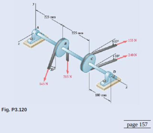
Replace the given system with its equivalent force-couple system at POINT A.
Answer to Problem 3.120P
The equivalent force is
Explanation of Solution
Refer Fig P3.120. Its vector diagrams showing equivalent force-couple is given below.
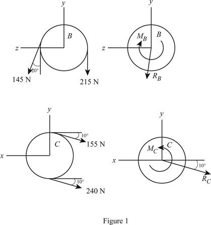
Write the formula to calculate the resultant force pulley B.
Here,
Write the formula to calculate the net moment of couple on pulley B.
Here,
Write the formula to calculate the resultant force pulley C.
Here,
Write the formula to calculate the net moment of couple on pulley B.
Here,
Write the expression to calculate the net force on pulley.
Here,
Write the expression to calculate the resultant moment of couple about point A.
Here,
Write the determinant form to calculate
Here,
Conclusion:
Substitute
Substitute
Substitute
Substitute
Substitute
Substitute
Calculate
Calculate
Rewrite equation (IIX) by substituting equations (IX) and (X).
Therefore, the equivalent force is
Want to see more full solutions like this?
Chapter 3 Solutions
EBK VECTOR MECHANICS FOR ENGINEERS: STA


- In order to design the foundation for the utility pole shown to the right, replace the system of three applied forces with an equivalent force- couple system applied at point A.arrow_forwardAn overhead view of a portion of an exercise machine is shown. If the tension in the cable is T = 750 N, determine the equivalent force-couple system at (a) point B and at (b) point O.arrow_forwardRight angle tube OAB shown. Replace the 20 N pulling force that the cable exerts at point B with a force-couple system at point O.arrow_forward
- 1. Determine the equivalent force-couple system at A of the system shown on the figure.arrow_forwardA 260-lb force is applied at A to the rolled-steel section shown.Replace that force with an equivalent force-couple system at the center C of the section.arrow_forwardThe force-couple system shown acts on a trapezoidal plate. a. Determine the value of M1 if the system shown is equivalent to a single force acting at point C. b. The system shown is equivalent to a force-couple system consisting of R and M2 = 3000 kip-in clockwise. If M1 in this case is 120 kip-in counterclockwise, determine the point of action of the resultant force R along line CD.arrow_forward
- As an adjustable brace BC is used to bring a wall into plumb, the force-couple system shown is exerted on the wall. Replace this force couple system with an equivalent force-couple system at A if R=21.2 lb and M=13.25 lb·ft.arrow_forwardThe pulley and gear are subjected to the loads shown. For these forces, determine the equivalent force-couple system at point ?.arrow_forward(a) Determine a wrench equivalent force-couple system (b) Specify the x and y coordinates of the point where the wrench crosses the xy plane please answer aarrow_forward
- Replace the 250-kN force P by an equivalent force-couple system at G.arrow_forward250 N 200 mm 20 mm E 40 mm 100 mm 50 N 160 mm 120 N 300 N Four forces are applied to the machine component ABDE as shown. Replace these forces with an equivalent force-couple system at A.arrow_forwardA 30-lb vertical force P is applied at A to the bracket shown, which is held by screws at B and C. (a) Replace P with an equivalent force-couple system at B. (b) Find the two horizontal forces at B and C that are equivalent to the couple obtained in part a. A -5 in. B C 2 in. 3 in.arrow_forward
 International Edition---engineering Mechanics: St...Mechanical EngineeringISBN:9781305501607Author:Andrew Pytel And Jaan KiusalaasPublisher:CENGAGE L