
Mechanics of Materials (10th Edition)
10th Edition
ISBN: 9780134319650
Author: Russell C. Hibbeler
Publisher: PEARSON
expand_more
expand_more
format_list_bulleted
Concept explainers
Videos
Textbook Question
Chapter 3.4, Problem 3.2P
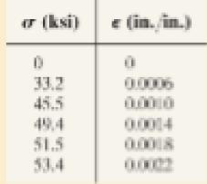
Data taken from a stress-strain test for a ceramic are given in the table. The curve is linear between the origin and the first point. Plot the diagram, and determine the modulus of elasticity and the modulus of resilience.
Expert Solution & Answer

Trending nowThis is a popular solution!

Students have asked these similar questions
You must perform mechanical tests with a linear elastic material (the material follows Hooke's law) applying forces (tension) in the range 0 to Fmax/2 for Sample A and between 0 to Fmax for Sample B. The samples are made of same material but have different geometries (see illustration). (a) Which of the two samples receives the maximum stress (σmax)? (b) Which of the two samples will have the larger length change (ΔLmax)? (c) Plot the expected curves for the two samples in the force-length and stress-strain planes. (d) Clearly indicate the values that the variables force, length, stress, and strain take at the beginning and end of each curve.
Natural rubber is tested in tension to a maximum extension ratio of λ = 3. The Mooney-Rivlin constants for this material are found to be C1 = 0.069 MPa and C2 = 0.125 MPa. Plot the corresponding uniaxial stress vs. extension ratio behavior over the tested range. Derive an expression for the slope of the function, then determine the secant and tangent moduli at 100% strain.
2) Find the strains in the 1-2 coordinate system (local axes) in a unidirectional boron/epoxy
lamina with 50% fiber volume fraction, if the stresses in the 1-2 coordinate system
applied to are ơ1 = 6 MPa, ơ2 =2 MPa, and T12 = -4 MPa. Use the properties of the given
unidirectional lamina in the book and assume plane stress conditions for the lamina.
Chapter 3 Solutions
Mechanics of Materials (10th Edition)
Ch. 3.4 - Define a homogeneous material.Ch. 3.4 - Indicate the points on the stress-strain diagram...Ch. 3.4 - Define the modulus of elasticity E.Ch. 3.4 - At room temperature, mild steel is a ductile...Ch. 3.4 - Engineering stress and strain are calculated using...Ch. 3.4 - As the temperature increases the modulus of...Ch. 3.4 - A 100-mm-long rod has a diameter of 15 mm. If an...Ch. 3.4 - A bar has a length of 8 in. and cross-sectional...Ch. 3.4 - A 10-mm-diameter rod has a modulus of elasticity...Ch. 3.4 - The material for the 50-mm-long specimen has the...
Ch. 3.4 - The material for the 50-mm-long specimen has the...Ch. 3.4 - If the elongation of wire BC is 0.2 mm after the...Ch. 3.4 - A tension test was performed on a steel specimen...Ch. 3.4 - Data taken from a stress-strain test for a ceramic...Ch. 3.4 - Data taken from a stress-strain test for a ceramic...Ch. 3.4 - The stress-strain diagram for a steel alloy having...Ch. 3.4 - The stress-strain diagram for a steel alloy having...Ch. 3.4 - The stress-strain diagram for a steel alloy having...Ch. 3.4 - The rigid beam is supported by a pin at C and an...Ch. 3.4 - The rigid beam is supported by a pin at C and an...Ch. 3.4 - Acetal plastic has a stress-strain diagram as...Ch. 3.4 - The stress-strain diagram for an aluminum alloy...Ch. 3.4 - The stress-strain diagram for an aluminum alloy...Ch. 3.4 - The stress-strain diagram for an aluminum alloy...Ch. 3.4 - A bar having a length of 5 in. and cross-sectional...Ch. 3.4 - The rigid pipe is supported by a pin at A and an...Ch. 3.4 - The rigid pipe is supported by a pin at A and an...Ch. 3.4 - Direct tension indicators are sometimes used...Ch. 3.4 - The rigid beam is supported by a pin at C and an...Ch. 3.4 - The rigid beam is supported by a pin at C and an...Ch. 3.4 - The stress-strain diagram for a bone is shown, and...Ch. 3.4 - The stress-strain diagram for a bone is shown and...Ch. 3.4 - The two bars are made of a material that has the...Ch. 3.4 - The two bars are made of a material that has the...Ch. 3.4 - The pole is supported by a pin at C and an A-36...Ch. 3.4 - The bar DA is rigid and is originally held in the...Ch. 3.7 - A 100-mm-long rod has a diameter of 15 mm. If an...Ch. 3.7 - A solid circular rod that is 600 mm long and 20 mm...Ch. 3.7 - A 20-mm-wide block is firmly bonded to rigid...Ch. 3.7 - A 20-mm-wide block is bonded to rigid plates at...Ch. 3.7 - The acrylic plastic rod is 200 mm long and 15 mm...Ch. 3.7 - The plug has a diameter of 30 mm and fits within a...Ch. 3.7 - The elastic portion of the stress-strain diagram...Ch. 3.7 - The elastic portion of the stress-strain diagram...Ch. 3.7 - The brake pads for a bicycle tire are made of...Ch. 3.7 - The lap joint is connected together using a 1.25...Ch. 3.7 - The lap joint is connected together using a 1.25...Ch. 3.7 - The rubber block is subjected to an elongation of...Ch. 3.7 - The shear stress-strain diagram for an alloy is...Ch. 3.7 - A shear spring is made from two blocks of rubber,...Ch. 3 - The elastic portion of the tension stress-strain...Ch. 3 - The elastic portion of the tension stress-strain...Ch. 3 - The rigid beam rests in the horizontal position on...Ch. 3 - The wires each have a diameter of 12 in., length...Ch. 3 - The wires each have a diameter of 12 in., length...Ch. 3 - diameter steel bolts. If the clamping force in...Ch. 3 - The stress-strain diagram for polyethylene, which...Ch. 3 - The pipe with two rigid caps attached to its ends...Ch. 3 - The 8-mm-diameter bolt is made of an aluminum...Ch. 3 - An acetal polymer block is fixed to the rigid...
Knowledge Booster


Learn more about
Need a deep-dive on the concept behind this application? Look no further. Learn more about this topic, mechanical-engineering and related others by exploring similar questions and additional content below.Similar questions
- A steel Column is 10m long and Ø1.2m. It carries a load of 102MN. Given the modulus of Elasticity is 256GPA. Find the stress, Strain, and determine how much the column is compressed. Label the following diagram to show Stress, Strain, Tensile Strength, Yield Strength and Rupture Strengtharrow_forwardA specimen of titanium alloy is tested in torsion and the shear stress–strain diagram is shown in Fig.a. Determine the shear modulus G, the proportional limit, and the ultimate shear stress. Also, determine the maximum distance d that the top of a block of this material, shown in Fig. b, could be displaced horizontally if the material behaves elastically when acted upon by a shear force V. What is the magnitude of V necessary to cause this displacement?arrow_forwardLet's consider a rod having a solid circular cross-section with diameter of 5 mm and it is made of a material having a Young's modulusE=120 Gpa and a Poisson's ratio of 0.33. If a tensile force F is subjected to that rod cross-section, the diameter becomes 4.995 mm. determine the applied force F.arrow_forward
- 2. Ten point load tests are carried out on cylindrical specimens of a sedimentary rock with 30 mm diameter, as shown in the figure. 50 mm The failure loads of these tests are equal to: 3.2, 4.1, 3, 3.8, 2.9, 4.2, 3.5, 3.6, 3.5 and 4 kiloNewtons. Determine Iso) of this rock. Predict the uniaxial compressive strength of this rock.arrow_forwardA tensile test specimen has a gage length = 3.0 in and diameter 0.75 in. Yielding occurs at a load of 38,000 lb. The corresponding gage length = 3.0103 in (neglect the 0.2 percent yield point). The maximum load of 54,000 lb is reached at a gage length = 3.453 in. Determine the modulus of elasticity (neglect the 0.2% offset, and round to the nearest whole Msi). 37arrow_forwardA copper rod with a diameter of 19 mm, modulus of 110 GPa, and a Poisson’s ratio of 0.35 is subjected to tension within the elastic region. Determine the force ( in N) that will produce a reduction of 0.003 mm in the diameter.arrow_forward
- A test specimen in a tensile test has a gage length of 2.0 in and an area = 0.5 in?. During the test the specimen yields under a load of 32,000 lb. The corresponding gage length = 2.0083 in. This is the 0.2 percent yield point. The maximum load of 60,000 lb is reached at a gage length = 2.60 in. Determine: (a) Yield strength (b) Modulus of elasticity (c) Tensile strength (d) If the specimen necked to an area = 0.25 in', determine the percent reduction in areaarrow_forwardThe principal plane stresses and associated strains in a 35 ksi, 02 = 15 ksi, plane at a point are 01 1 €1 = 1.02(10-3), 2 = 0.180(10-³). ▼ Determine the modulus of elasticity. Express your answer using three significant figures and include the appropriate units. E= Submit Part B V= μA Value Request Answer Submit Determine the Poisson's ratio. Express your answer using three significant figures. ΠΑΠΙ ΑΣΦ | Η VE Units Request Answer ? vec POSSIA space ?arrow_forwardDetermine the elastic tensile load "F" that acts on mild steel specimen of Diameter 8 mm & Modulus of Elasticity 201 GPa. It is found that the specimen has undergone an extension of 1.6 mm due to the elastic load "F". Also, determine the length "L" of the specimen, if the strain-induced due to the load "F" on the specimen is 4.1 x 10⁻³. Solution Cross-sectional Area, A (in mm²) Tensile Load, F (in N) Length of the Specimen (in mm)arrow_forward
- Determine the elastic tensile load "F" that acts on mild steel specimen of Diameter 7 mm & Modulus of Elasticity 192 GPa. It is found that the specimen has undergone an extension of 1.2 mm due to the elastic load "F". Also, determine the length "L" of the specimen, if the strain-induced due to the load "F" on the specimen is 4.2 x 10-³. Solution Cross-sectional Area, A (in mm²) = Tensile Stress, (in N/mm²): Tensile Load, (in N) = = Length of the Specimen (in mm)arrow_forwardThe length of a wire increases from 1.25 m to 1.2508 m when a load of 12 kg is suspended. The radius of the wire is 0.5 mm. Find the stress, strain and young's modulus of material of the wire. Draw a free body diagram.arrow_forwardThe stress-strain diagram of a reinforcement steel having a cross-sectional diameter of 12 mm diameter and 100 mm gage length is determined after its tensile strength test as follows. Based on the stressstrain diagram determine the followings properties of the material (Poisson’s ratio of the material is 0.32) :arrow_forward
arrow_back_ios
SEE MORE QUESTIONS
arrow_forward_ios
Recommended textbooks for you
 Elements Of ElectromagneticsMechanical EngineeringISBN:9780190698614Author:Sadiku, Matthew N. O.Publisher:Oxford University Press
 Mechanics of Materials (10th Edition)Mechanical EngineeringISBN:9780134319650Author:Russell C. HibbelerPublisher:PEARSON
 Thermodynamics: An Engineering ApproachMechanical EngineeringISBN:9781259822674Author:Yunus A. Cengel Dr., Michael A. BolesPublisher:McGraw-Hill Education
 Control Systems EngineeringMechanical EngineeringISBN:9781118170519Author:Norman S. NisePublisher:WILEY
 Mechanics of Materials (MindTap Course List)Mechanical EngineeringISBN:9781337093347Author:Barry J. Goodno, James M. GerePublisher:Cengage Learning
 Engineering Mechanics: StaticsMechanical EngineeringISBN:9781118807330Author:James L. Meriam, L. G. Kraige, J. N. BoltonPublisher:WILEY
Elements Of Electromagnetics
Mechanical Engineering
ISBN:9780190698614
Author:Sadiku, Matthew N. O.
Publisher:Oxford University Press
Mechanics of Materials (10th Edition)
Mechanical Engineering
ISBN:9780134319650
Author:Russell C. Hibbeler
Publisher:PEARSON
Thermodynamics: An Engineering Approach
Mechanical Engineering
ISBN:9781259822674
Author:Yunus A. Cengel Dr., Michael A. Boles
Publisher:McGraw-Hill Education
Control Systems Engineering
Mechanical Engineering
ISBN:9781118170519
Author:Norman S. Nise
Publisher:WILEY
Mechanics of Materials (MindTap Course List)
Mechanical Engineering
ISBN:9781337093347
Author:Barry J. Goodno, James M. Gere
Publisher:Cengage Learning
Engineering Mechanics: Statics
Mechanical Engineering
ISBN:9781118807330
Author:James L. Meriam, L. G. Kraige, J. N. Bolton
Publisher:WILEY
Material Properties 101; Author: Real Engineering;https://www.youtube.com/watch?v=BHZALtqAjeM;License: Standard YouTube License, CC-BY